question

colin-mackay avatar image
colin-mackay asked

ESS system not using all PV and battery power available?

Good Day

I have a 3 Phase ESS system with 3 x 10KvA Quattros, 5 x 250v 100a VE Can MPPTs and 560ah of lead acid battery,

Scenario 1)

When set on Battery Life - self consumption - Min SOC 80%-no feedback- the system works well until battery reaches 80% SOC. At this stage the system reverts to feeding from grid directly to load and solar array reduces to almost nil.

Why is solar not supplying load? - There is plenty of sun


Scenario 2)

Same settings - battery at 91.5%, solar putting out 5622w, load is at 9890w. 790w is being taken from battery and 4756w is being taken from grid.

Why is battery not supplying load?

I have a feeling there is an incorrect setting somewhere but cannot find it.

Any Ideas

ESS
2 |3000

Up to 8 attachments (including images) can be used with a maximum of 190.8 MiB each and 286.6 MiB total.

4 Answers
nickdb avatar image
nickdb answered ·

when you hit the minimum ess soc the system dedicates all solar to charging the batteries until it gets near the stop on charge limit set in the schedule.

you can reduce this second limit to allow it to cut back sooner.


2 |3000

Up to 8 attachments (including images) can be used with a maximum of 190.8 MiB each and 286.6 MiB total.

Guy Stewart (Victron Community Manager) avatar image
Guy Stewart (Victron Community Manager) answered ·

Hi @Colin mackay,

That is an ENORMOUS system in a tiny battery.

Your system has the potential to pull 30 kW, that is ~600 A from a 560 Ah battery. This sizing would be ok for a lithium battery, but not for lead acid.

A regular (off grid) system design would be to have 5000 Ah of lead acid battery for such a load. 10 times as much.

A nice, safe, reliable charge and discharge rate for lead acid is C10, or 10% of it's Ah capacity in A.

It is very likely that your battery, if it is engaged at all by the charging (or discharging system) beyond that C10 (55A from a 550Ah battery, or ~2500W) will cause the battery voltage to behave very erratically, spiking high and low.

The system relies on a relatively stable battery voltage to make decisions about when to charge, discharge, load, pass thru power, trigger warnings or alarms.

It is going to be very difficult to make a stable system from this design, with very large potential load demand, PV supply and very small battery. The grid will be doing a lot more work, and will be supplying the system more often than necessary. Also at times, the PV may start to charge the battery, and the voltage will spike up very quickly, leading the PV to quickly back off.

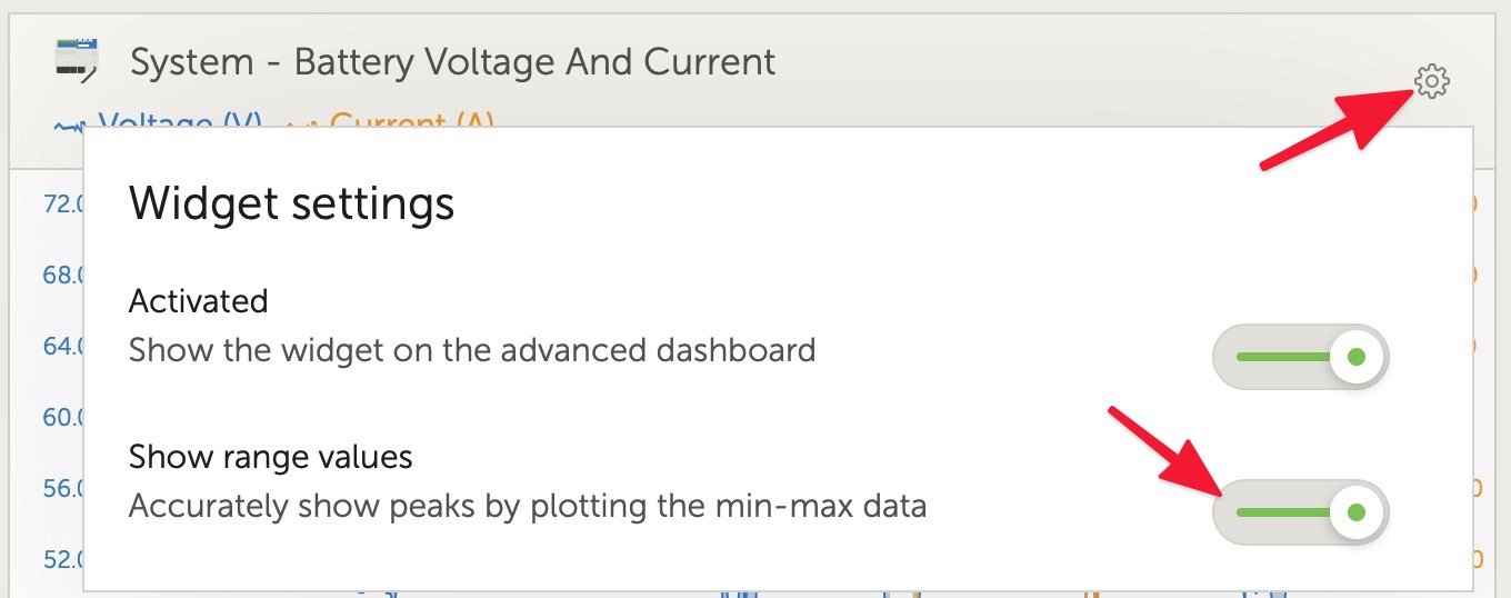
Have a look at the Advanced tab DC battery voltages in VRM to see if you can see the effect I am talking about. If the battery reaches full voltage (~55V) or minimum voltage (~49V) it will adjust its behaviour to to protect the battery, (reducing PV, or preventing discharge from the battery).

These are higher priority triggers and will happen regardless of the reported State of Charge, or the thresholds.

Be sure to turn on the Maximum & minimum view with ~1 minute interval recording on the GX to help see.

These large voltage spikes also might be occurring too quickly to see, so also check the real time view (~2 seconds) around when it is likely to occur.


1 comment
2 |3000

Up to 8 attachments (including images) can be used with a maximum of 190.8 MiB each and 286.6 MiB total.

colin-mackay avatar image colin-mackay commented ·

I do see exactly what you're saying. The new battery will be 1500ah tubular gel so should improve performance.


0 Likes 0 ·
maha avatar image
maha answered ·

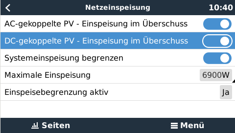
Have you switched on "DC..."?


1602837749439.png (24.0 KiB)
2 |3000

Up to 8 attachments (including images) can be used with a maximum of 190.8 MiB each and 286.6 MiB total.

colin-mackay avatar image
colin-mackay answered ·

Hi all - thanks for your answers.

The current battery is temporary only. We have resolved the issue -- the installer had each inverter connected to a seperate string of batteries -So each inverter was reading and discharging seperate parts of the battery. The system is now working perfectly.

My biggest issue now is the temperature that the MPPTs are running at. The ambient (managed by aircon) is around 23 degrees. The MPPT temperatures range from 42 degrees C to 53 degrees C - is this normal - it seem a little on the high side to me. Any ideas Guy?


1 comment
2 |3000

Up to 8 attachments (including images) can be used with a maximum of 190.8 MiB each and 286.6 MiB total.

Great to hear things are improving.

The MPPTs are designed to self regulate their temperature - though please make sure that they are running the latest firmware version. There was an improvement to the temperature self-regulation.

Normally they do get warm, there is a lot of power flowing through a relatively small package. Adding some airflow over their heatsink will reduce their temperature if you want.

0 Likes 0 ·

Related Resources

Additional resources still need to be added for this topic