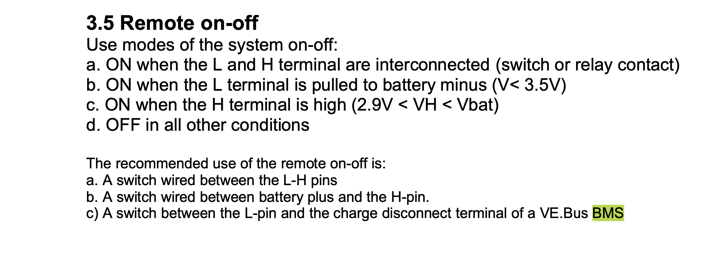
I am about to install the above model into my system comprising a Cerbo and Smart Lithium Batteries with a VE.Bus BMS. I have been reading the manual in preparation and found the following regarding the BMS connection.

I am surprised that it suggest the VE.Bus BMS charge disconnect is connected to the L-Pin. The VE.Bus BMS will supply a high signal until a charge disconnect event occurs when the signal will drop too floating. In all other devices the VE.Bus BMS is therefore connected to the H-Pin. Even the description of the use of the L and H terminal match that in all other manual, and implies it should be connected to the H pin.
Could someone advise if this is a typo in the manual and the VE.Bus BMS should indeed be connected to the H Pin of the Smart Solar MPPT 150/70 VE.Can?
Many Thanks
