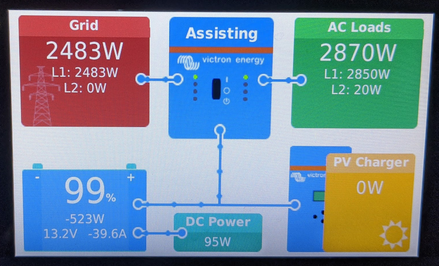
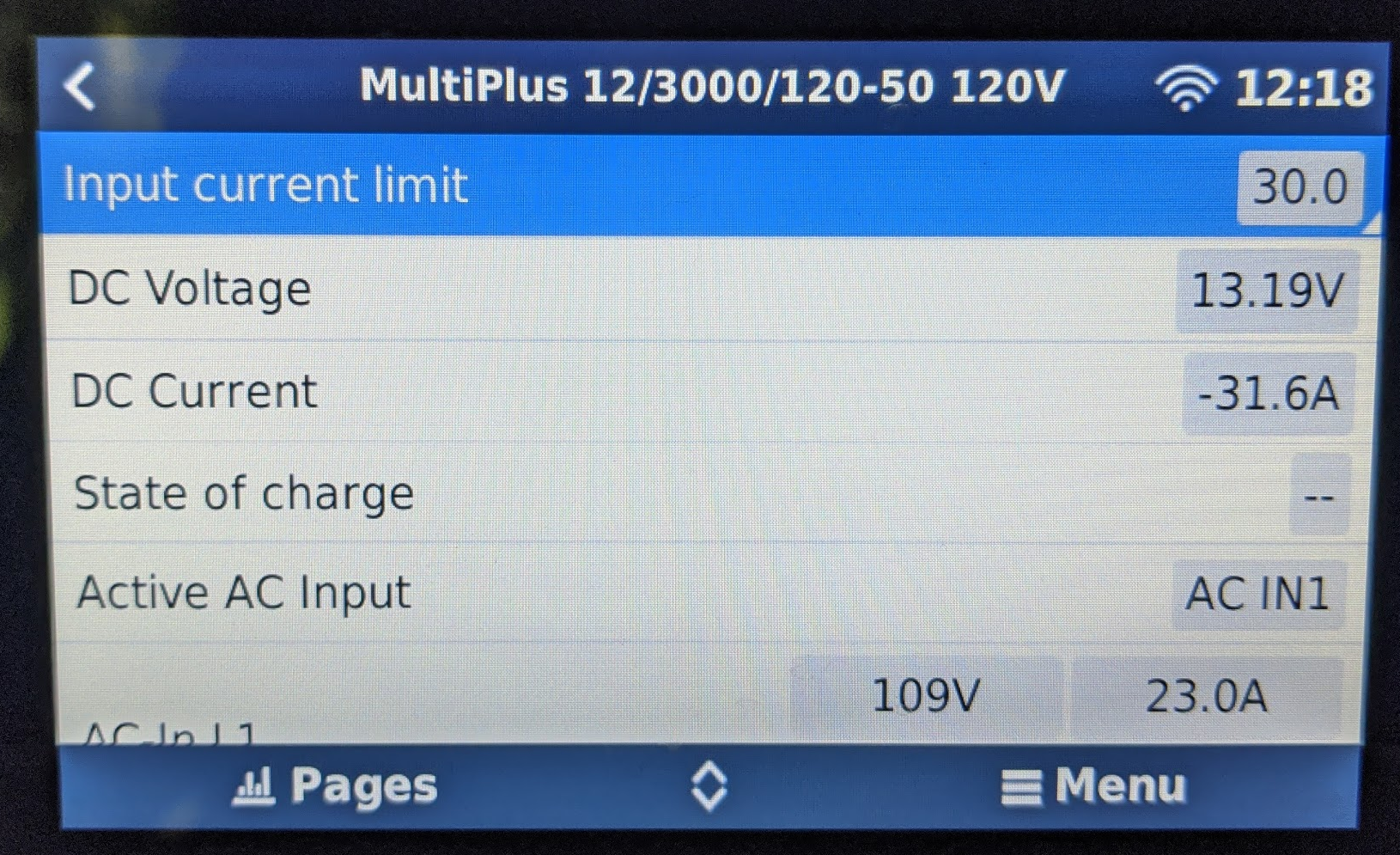
The power system (components listed here; all devices have the latest firmware as of this posting) I installed in my fifth wheel is entering power assist mode despite the AC input being less than the input current limit. For background, one goal of this system was to be able to run a pair (15 and 13.5 kBTU/hr) of air conditioners on 30A/120VAC single phase service, with the inverters/batteries supplementing the grid power for intermittent loads like a Keurig, microwave, etc. The trailer came with one air conditioner on L1 and the other on L2. Of course, when only single phase input is provided, the second inverter inverts from 12 VDC but its continuous output must of course be limited by the first inverter's charging capacity of 120A. After conversion losses this is inadequate to power the second AC without pulling from the batteries (side note for any Victron employees lurking: *please* implement a way for the second inverter in a split-phase system to accept AC input that's in-phase with the first inverter! This is obviously something that can be done in software and its absence is driving customers with RV applications out of their minds). To get around this problem I installed a 20A switch that allows me to switch the second air conditioner from L1 to L2. I thought that was clever.
But not really; the stubbornness of the Multiplus defeats my ingenuity. See pics below.


As you can see, it is drawing well below the input current limit from the grid, yet "assisting" and drawing down my batteries. The total draw is around 28-29A although it can't be seen in the pictures (but you can infer it from the "AC Loads").
Please help me figure out how to force the inverter to draw up to the input current limit before it goes into assist mode; I really can't stomach the thought that I paid ~$15k and put in dozens of hours of work to actually lose capability.
Edit: The system is plugged into a 30A 120/240VAC split-phase connection. Inside the rig I have a 50A breaker upstream of the Multis, and I cut the little metal link joining the two poles of the breaker so that I can switch L1 and L2 on/off separately. In the example above, L2 is cut off to simulate how the Multis behave when only given a 30A/120VAC input (the first inverter switches to grid input while the second simply inverts from the batteries, as I ranted about in bold above). It is connected through several long extension cords, hence the voltage drop. Nevertheless, there is sufficient input amperage available to power these loads from grid input alone (and it certainly should be pulling more than 23A when it has a 30A input current limit).
Here's a VRM link: https://vrm.victronenergy.com/installation/66058/share/6019a575
And here's a link to the RVMS file with the current inverter configuration: https://drive.google.com/file/d/1JUNAxmPHIBWKNB6Saglhysvo8FdTxRsx/view?usp=sharing
Thanks!
