question

Alex Bell avatar image
Alex Bell asked

Multiplus 12/3000/120 Frequent Low Battery Alarm Shutdown

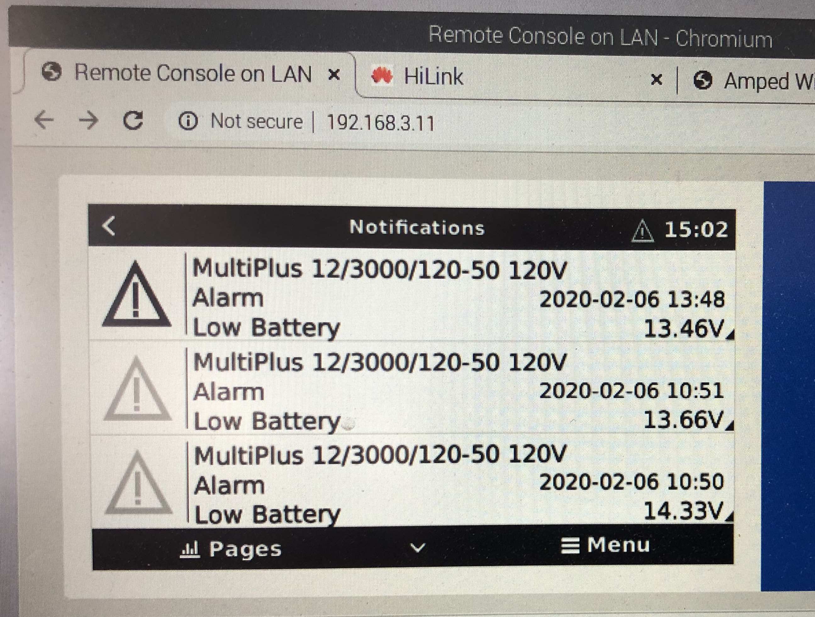
When we turn on the microwave or water heater, each draws about 1200w, 2 out 3 times the Multiplus shuts down with a Low Battery Alarm. The voltage shown on the Alarm message on the Venus GX display ranges from 14.51v to 12.37v -- see photo below, there does not appear to be low voltage. The ripple gets to 1.0 -- see video below. The shutdowns seem to be getting more frequent. Most of the time the Multi does not revive itself and has to be switched off and on. Getting lots of sun (over 1000w of solar power) does not seem to make any difference. Everything is running the latest software.

1 - Multiplus 12/3000/120-50

1 - Venus GX

1 - BMV 700

7 - Trojan Trillium (lithium) 12v batteries total 770Ah

5 - Blue Solar 100/30 controllers

5 - LG Neon 350w solar panels total 1750w
MultiPlus Quattro Inverter Chargerlow battery warning
img-8381.jpg (547.2 KiB)
1 comment
2 |3000

Up to 8 attachments (including images) can be used with a maximum of 190.8 MiB each and 286.6 MiB total.

Alex Bell avatar image Alex Bell commented ·

Here is a description of the wiring.

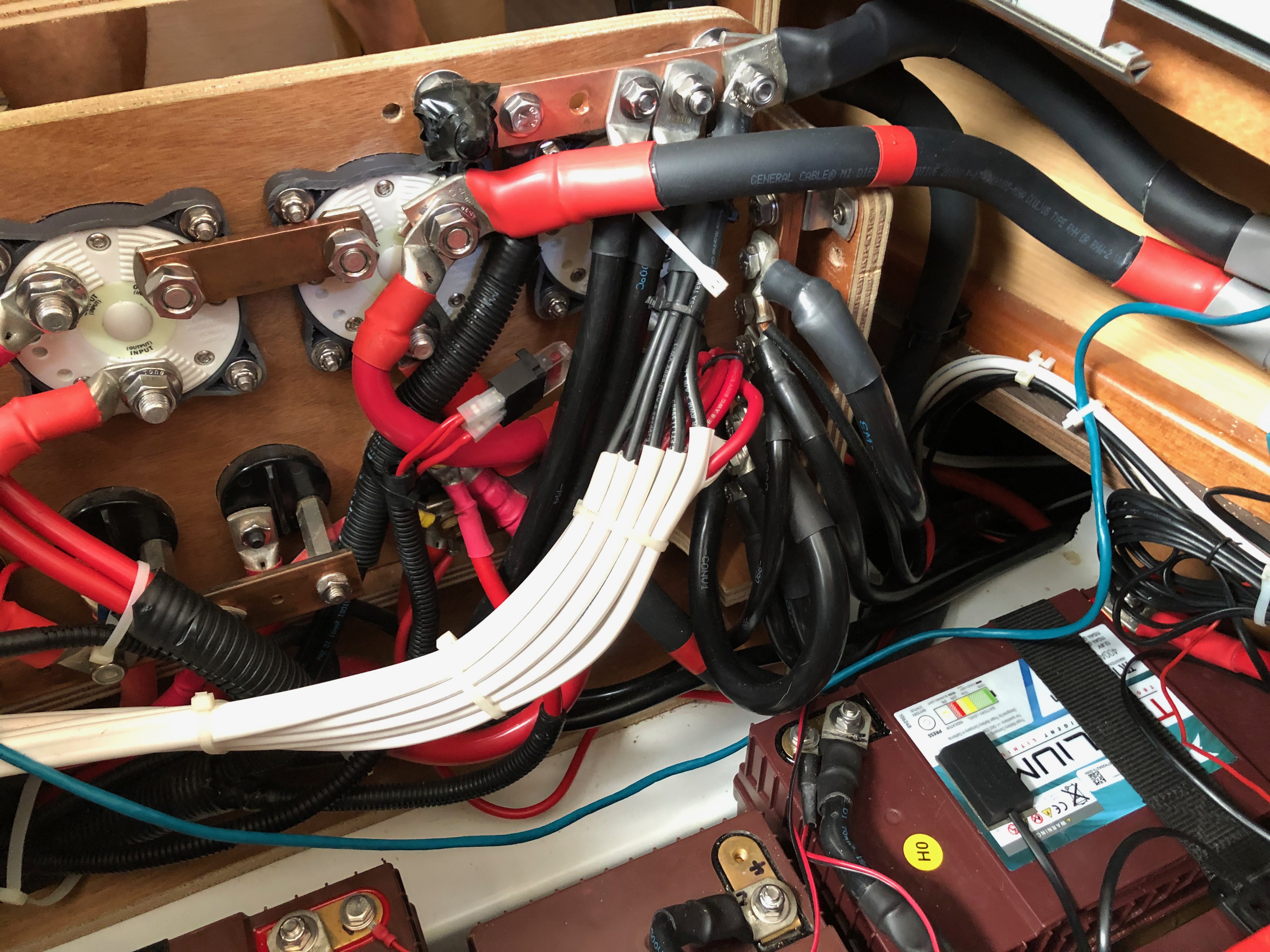
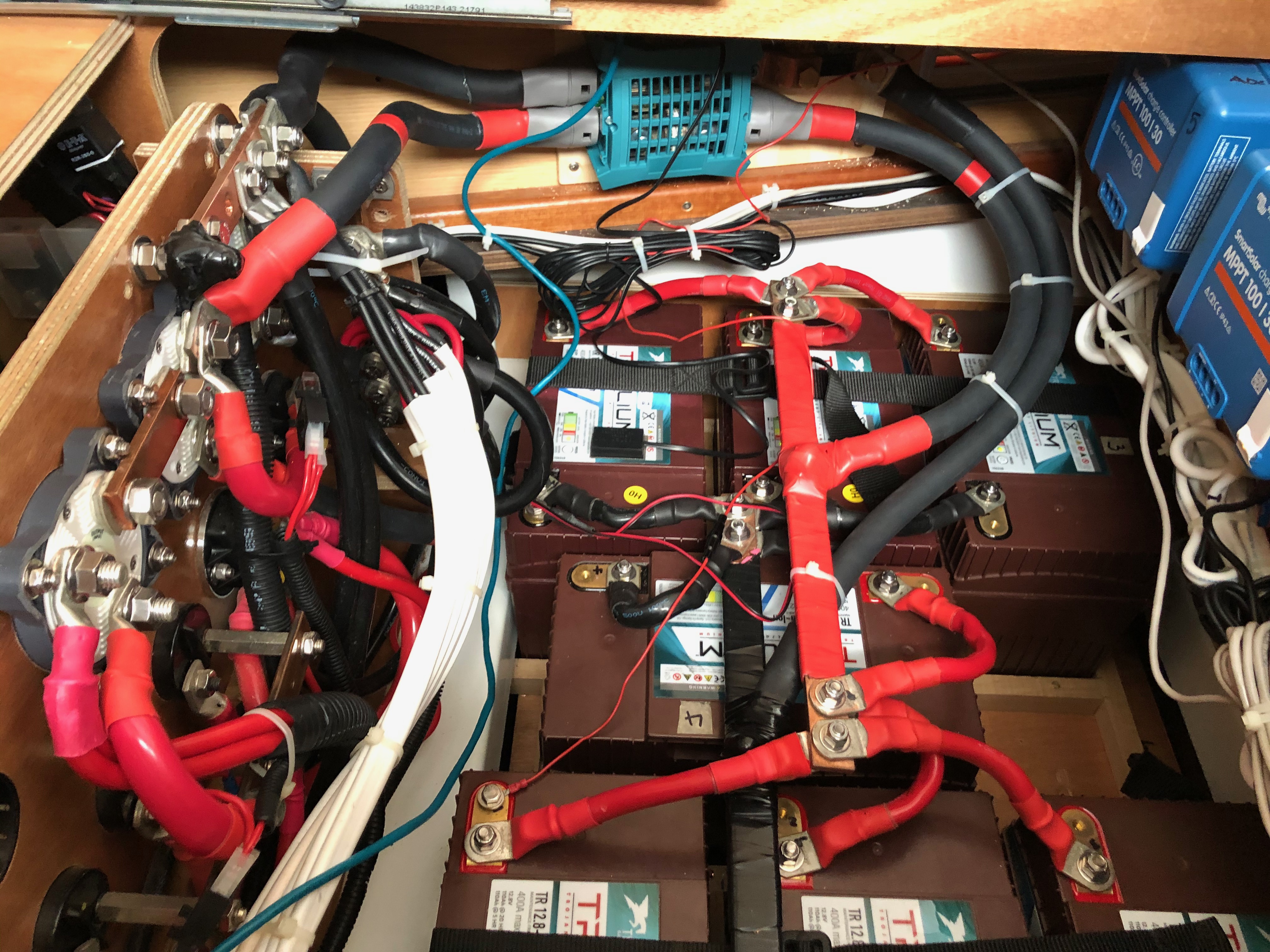
Batteries Pos (+) - 70mm for 1.0m - BMV 700 - 70mm for 1.0m - Battery Switch - 35mm for 0.3m - Copper Bus Bar (0.5cm x 4cm) - 95mm for 1.5m - 300A Fuse - 95mm for 0.5m - Multiplus Pos (+)

Batteries Neg (-) - 70mm for 2.0m - Battery Switch - 35mm for 0.3m - Copper Bus Bar (1cm x 2cm) - 95mm for 2.0m - Multiplus Neg (-)


0 Likes 0 ·
3 Answers
Justin Cook avatar image
Justin Cook answered ·

@ralexbell, do I read this correctly that you have a 35mm2 (2AWG) wire connecting your battery switch to your busbar on both the POS and NEG connections?

If so, that's the problem and must be corrected immediately; the minimum cable gauge that should be used anywhere in the circuit between a MultiPlus and its batteries is 70mm2 (2/0AWG) and in fact it's generally recommended to use (2) 2/0 wires (thus why there are two POS and two NEG connection posts inside the MultiPlus) or one 4/0 cable.

Using any length of 35mm2 cable in the circuit will create a massive -and very dangerous- voltage drop along that length, particularly when running your Multi under heavy load.

This will not necessarily be reflected in your battery voltage readings because the problem isn't at the battery - the problem is that the Multi isn't getting the voltage it needs. It's shutting down because it is experiencing under-voltage, not because your batteries are under-voltage.

Also, I just want to confirm a couple of things:

1. In your post of your wiring, you list the BMV shunt on the POS side... I want to make sure that's a typo, since the shunt goes on the NEG side.

2. I don't see a fuse at the battery on the POS side listed anywhere. Hopefully you just left that out of your list, but if you don't have a fuse on your POS line at the battery, please immediately install an appropriate fuse. Generally this is a 400A fuse - either ANL or Class T, though this fuse size is determined by the cabling you're using to connect the device since the fuse exists to protect your wiring, not particularly the device.

In sum: The MultiPlus should be immediately disconnected and the installation corrected, with the appropriate-gauge (2/0 minimum, 4/0 strongly recommended) cable installed on both the POS and NEG lines, an appropriate fuse installed at the battery on the POS line, and the BMV shunt correctly installed. When the system is connected properly, I am sure that this error will no longer be seen.

I urge that you contact a qualified and experienced DC systems installer to assist you with this. Improper installation of components will lead to component malfunction (as you can tell), premature failure, and can also pose a significant risk to personal and property damage.

For reference:

MultiPlus Manual

BMV-7xx Manual


6 comments
2 |3000

Up to 8 attachments (including images) can be used with a maximum of 190.8 MiB each and 286.6 MiB total.

Alex Bell avatar image Alex Bell commented ·

Yes. The BMV 700 is on the negative side.

The 35mm2 wires are now swapped with 70mm2. The new wires are 0.5m long and I don’t have any lugs — can’t shorten them at the moment.

With the 70mm wires here is the voltage at various locations with a 1300w load.

Batteries 13.00v — 70%, 258 Ah Consumed.

Switches 12.82v and 12.67v — battery side and load side

Bus Bars 12.61v

Multiplus 12.41v

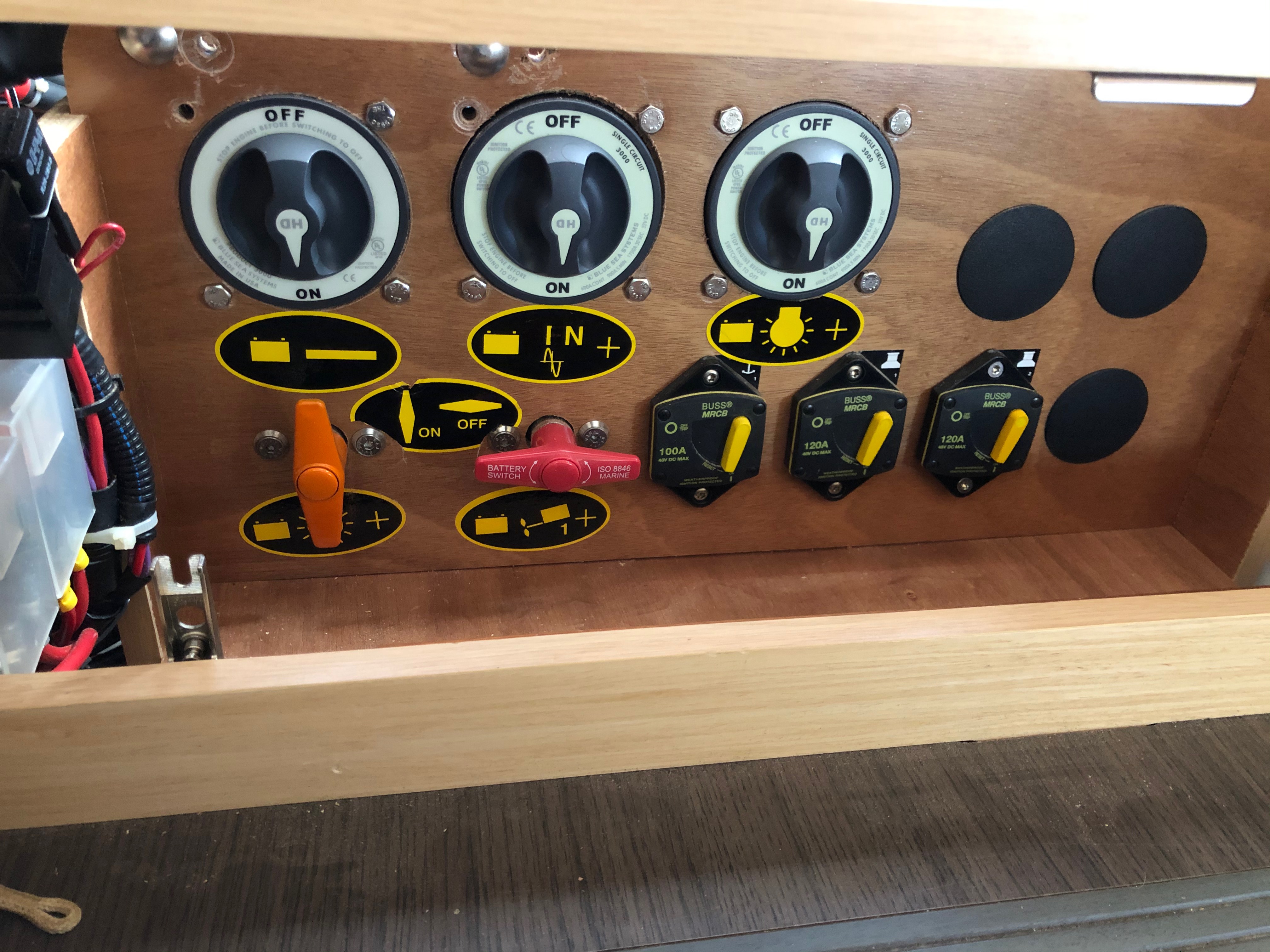
Note: With 70mm wires the Multi still shuts down randomly when a load is turned on. After 30 minutes the negative battery switch was 46 degrees C. The positive switch was 38 degrees. Other connections were low 30s. The air is 25 degrees. Clearly the switches are a bottleneck and I will upgrade them next.


0 Likes 0 ·
Justin Cook avatar image Justin Cook ♦♦ Alex Bell commented ·

@ralexbell, that's certainly better, but yes... the switches getting hot is either an indication of bad switches or loose connections - a loose DC connection generates heat, heat generates resistance, resistance = voltage drop, and it's a downward spiral from there.

Replacing the switches is a good idea, and also check your lug crimps; you should be able to put your full weight on a good crimp without it moving. If it moves, it was loose and should be redone. Also check all your connecting nuts/etc... if a nut on a connecting bolt or at the battery isn't torqued properly, it too will generate heat which raises resistance and on and on.

Overall I think you're on the right track though, so once you replace the switches, check your crimps and your cable attachment torques, you should start seeing much better performance out of your system.

0 Likes 0 ·
Daniël Boekel (Victron Energy Staff) avatar image Daniël Boekel (Victron Energy Staff) ♦♦ Justin Cook ♦♦ commented ·

@ralexbell

Also ask yourself if you really need a switch...and...why do you need two switches?

Every extra item is more losses.

0 Likes 0 ·
brucesterj avatar image brucesterj commented ·
Hi.. I see that you've got some knowledge about these Multiplus units. I recently had a 12v 3000 120 installed in my RV. It works but I can't get it configured to use less AC and more Solar. Can you answer some questions for me..?
0 Likes 0 ·
JohnC avatar image JohnC ♦ brucesterj commented ·
@Brucesterj

Just go back to the start and hit 'Create' to ask your questions. The better the detail you give about what you want, the better the answers are likely to be..

1 Like 1 ·
brucesterj avatar image brucesterj JohnC ♦ commented ·

Sorry, wrong approach.

0 Likes 0 ·
JohnC avatar image
JohnC answered ·

Hi @ralexbell

I suspect your alarms registered in your first screen are 'Pre-alarms', the actual shutdown coming at a lower V. Nor would I get too excited about the V reported, could be just a 'sample time' thing.

If you look in the Inverter tab of VE,Config, what are they set to? It's all very well trying to protect your expensive Li's by handling them with kid-gloves, but you can overdo this in the real world where an odd 'spike' could shut you down.

Seems 12.5V is where your video baulks. If it's set to shutdown there, try it a little lower.

Wiring/junction health should be visible between your Multi's and BMV's readings of V. Is there actually a real difference?

2 |3000

Up to 8 attachments (including images) can be used with a maximum of 190.8 MiB each and 286.6 MiB total.

Alex Bell avatar image
Alex Bell answered ·

** UPDATE ** All the wire is now 262 mcm Diesel Locomotive Cable (135mm2) with crimped and soldered lugs, and the switches are 600A. The low voltage warning light still flashes but we have not had a random low voltage error shutdown since -- several months :-).


img-0010.jpeg (2.1 MiB)
img-0006.jpeg (2.4 MiB)
img-0005.jpeg (2.6 MiB)
2 |3000

Up to 8 attachments (including images) can be used with a maximum of 190.8 MiB each and 286.6 MiB total.