question

rhen avatar image
rhen asked

Problem for 1st use of Si-RS485TC solar sensor with CCGX, Venus 2.40, Victron RS485-USB converter

Hello,

I discovered with a great interest this new and really intersesting possibility mentioned in the v2.40 change log, opening the door to a measurement and datalogging of the really available solar energy, not only what the regulators and batteries can take.

And I directly procured the Si-RS485TC sensor through IMT gmbh for trying to install it on the field.

But I don't understand some recommendation given by IMT, who let think that a software preparation is needed (connecting to a PC with their specific Modbus configurator and a specific ICPCON I-7561 or DIGITUS DA-70157 RS485-USB conventer) for changing some Modbus parameters.

Is that really needed, before coupling their Si-RS485TC sensor with the CCGX through the Victron standard RS485-USB converter ?

With the v2.40, is their Si-RS485TC sensor not directly, plug and play recognized through the Victron RS485-USB converter ?

Any help, and especially a Victron application note should be welcome for a first use (especially for people who, so as me, are not expert in RS45 and Modbus)

Kind regards

RHEN

CCGX Color Controlrs485
2 |3000

Up to 8 attachments (including images) can be used with a maximum of 190.8 MiB each and 286.6 MiB total.

2 Answers
mvader (Victron Energy) avatar image
mvader (Victron Energy) answered ·

Dear Roland, documentation on how to connect and configure the sensor and your GX device is here: https://www.victronenergy.com/live/ccgx:start#connecting_imt_solar_irradiance_temperature_and_wind_sensors .


No configuration should be necessary, however as also discussed between you and me by email there might be something. I am clearing that up together with the IMT company and will report back here once clear.

No application note should be necessary, it should all be really simple. Let me summarise it here:

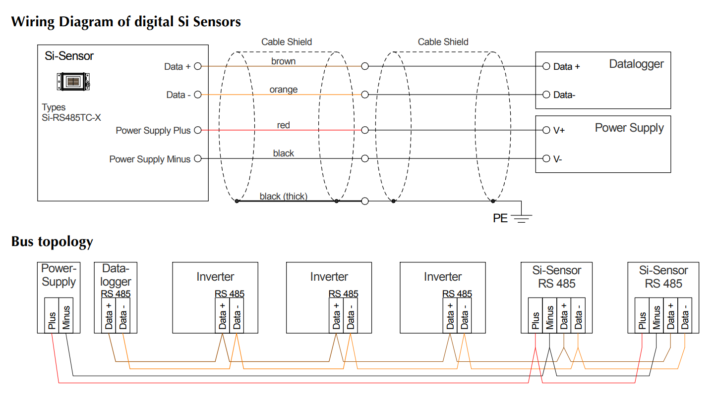
The sensor requires a minimum of four wires, and ground:

(copied from the sensor manual).


The Inverters in that lower diagram can be ignored, you can't combine this onto a Victron RS485 bus. Also you can't combine multiple Si-Sensor RS485 sensors on one bus, our software supports only one. So, as also explained in the manual, to use multiple sensors, one will need to add multiple USB to RS485 converters.


Then the Si-Sensor needs to be powered with 12 or 24V. Take the power from the same power supply that is powering the GX Device; and in case its a 48 Volt system, use a non isolated 48 to 24V DCDC Converter, with its input in parallel to the GX Device, and output connected to Si-Sensor. BEWARE! might be that max input voltage is 28V, which is too low for a 24V battery system, so then also for 24V systems, use an Orion DCDC Converter.

Wire connections:

Si-Sensor
RS 485 interface Signal Note
Black Black Minus Connect to GX Device minus as well.
Brown Orange RS485 Data A +
Orange Yellow RS485 Data B -
Black (thick)
Ground Ground
Red
Power positive (12/24V) Connect to either battery or output of DCDC Converter


Besides the Sensor manual linked above, I used the USB RS485 datasheet, to make above table.

Make sure all unused wires of the RS485 USB interface are terminated in an isolated manner.


Lastly: in case you prefer to use an isolated RS485 converter to wire the sensor into your GX device, use the USB485-STIXL : Isolated USB to RS485 converter from Hjelmslund Electronics. Don't use any others, not anything works, most or all others won't, since they will not be recognised by the GX Device.

When to use an isolated RS485 interface one might ask? Well, perhaps in case of a positive grounded system, but I'd need to draw that out to make sure. And another reason could be to be more resistant to damage due to lightning. The Hjelmslund STIXL offers 2500 Volt isolation. I'm quite sure that won't be enough for a direct hit; but, it will most probably still help in case of strikes in the vicinity.


1576876798118.png (172.1 KiB)
1 comment
2 |3000

Up to 8 attachments (including images) can be used with a maximum of 190.8 MiB each and 286.6 MiB total.

mvader (Victron Energy) avatar image mvader (Victron Energy) ♦♦ commented ·

ps; updated above text with notes about using an isolated rs485/usb interface

0 Likes 0 ·
rhen avatar image
rhen answered ·

Thank's a lot Matthijs for such detailed and very useful information.

If y cannot procure for the moment the recommended 48V to 24V converter solution, may I temporarily use for supplying the IMT sensor an isolated 230V-AC / 24V-DC adapter ?
(I have such DIN-rail power supply module available where I plan to connect with the CCGX)

If yes, is it mandatory in such case to connect the negative (-) wire of the power supply adapter with the negative (-) of the CCGX DC supply input ?
(the CCGX being at the moment supplied from a 48V battery, the negative (-) of the battery being floating)

2 |3000

Up to 8 attachments (including images) can be used with a maximum of 190.8 MiB each and 286.6 MiB total.

Related Resources

Additional resources still need to be added for this topic

CCGX Product Manual

CCGX Product page