question

cyotani avatar image
cyotani asked

Battery protect BP220 Remote Control Terminal Not Working

I have a battery protect with the input wired to a 24V LiPo4 battery bank and the output wired to an inverter. The ground is connected to the negative battery terminal and its programmed as 8A.


When I connect the battery for the first time with the remote terminal jumped, the inverter has 24V. When I disconnect the Remote jumper the inverter continues to have 24V.


When I disconnect then reconnected the battery with the Remote jumper removed the inverter still sees 24V.


Any idea what is happening? It looks like my remote circuit is not functioning at all.

Battery Protect
3 comments
2 |3000

Up to 8 attachments (including images) can be used with a maximum of 190.8 MiB each and 286.6 MiB total.

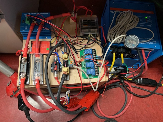
Please post some pictures of the installation.

0 Likes 0 ·
cyotani avatar image cyotani Guy Stewart (Victron Community Manager) ♦♦ commented ·

The left Anderson connector goes to the LifePo4 battery. The right Anderson connector goes to the inverter. I am wanting to use the BMS to trigger the batter protect via the remote terminal but currently, it is only wired to the relay module to disconnect the solar panels.

0 Likes 0 ·
img-6252.jpg (150.0 KiB)
best-lithium-battery avatar image best-lithium-battery commented ·

Hi, you have done a very simple mistake.. You need to reprogram BP220 to C, for example 8C (but the figure doesn't matter, when C the BP220 will act as a pure relay and controlled by remote).

0 Likes 0 ·
3 Answers
ron-laureltec avatar image
ron-laureltec answered ·

Item #4 in the Installation manual:

4. The SBP automatically detects the system voltage one time only after connection of plus and minus to the battery. The selected voltage (12 or 24V) is stored, and further automatic detection is disabled. See  in the programming table for how to reset it when re-using the SBP in a different installation or use Bluetooth.

1 comment
2 |3000

Up to 8 attachments (including images) can be used with a maximum of 190.8 MiB each and 286.6 MiB total.

cyotani avatar image cyotani commented ·

Thank you for the reply. I did have that issue at first. It was programmed as 12V and was throwing errors. I programmed it to "D" per the manual and it reset it as 24V and the error went away.


Removing the remote jumper should disconnect the battery regardless of what voltage it is set to and that currently is not working.

0 Likes 0 ·
ben avatar image
ben answered ·

It is possible that you have blown your BP220. It is not a good idea to run any lithium battery through a BP to an inverter, because the inrush current is very high. That current can destroy the FETs inside the BP, and then it fails closed-circuit.

That may not be what is going on in your case, but no matter what you discover, you should try not to use a BP as an isolator between a battery and an inverter. It will work until one day it does not, and you'll have no way to know because of how it fails.

2 |3000

Up to 8 attachments (including images) can be used with a maximum of 190.8 MiB each and 286.6 MiB total.

Justin Cook avatar image
Justin Cook answered ·

I'll mention a couple of things here: first, as @ben has stated, it's very possible that you've blown your BatteryProtect... you say that your inverter is "seeing" 24v when you unplug the remote jumper; do you mean that it's still powered on? If that's the case, then the BP is definitely faulted, as you're correct that all loads (not battery) should be automatically disconnected when you unplug the remote jumper. It's possible, however, to see voltage but no current - that is, you could be measuring 24v but only have a few mA of actual current, which would not necessarily indicate a fault in the BP. In that case, however, the inverter would not be powered. Bottom line: if you unplug the jumper and your inverter is still running, the BP is faulted. If you unplug the jumper and the load (inverter) disconnects and you're seeing 24v but only a few mA of current, then it's probably still fine.

In either case, I concur with Ben that the BP shouldn't be used between a battery bank and an inverter; depending on your inverter, you may well be over-amping the BP (I can't tell what model it is in the picture) and the high inrush can lock the FETs "open" or "closed"; furthermore, every Victron inverter I know of already has a user-settable low-battery cutoff, so it's just unnecessary to add this component.

One last thing I'll mention is that the way you have your wiring connected to the BMV shunt is going to give you inaccurate readings. The only cable that should be on the "Battery" side of the shunt is the cable going to the batteries. ALL other grounds should run off the "Load" side of the shunt, absolutely zero exceptions.

3 comments
2 |3000

Up to 8 attachments (including images) can be used with a maximum of 190.8 MiB each and 286.6 MiB total.

cyotani avatar image cyotani commented ·

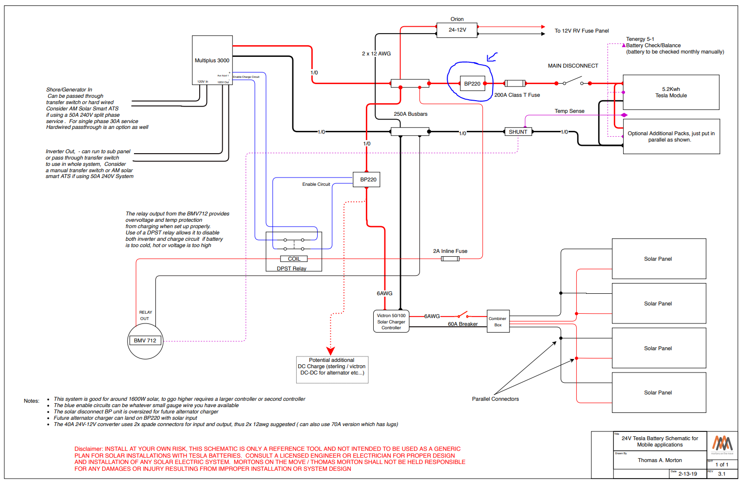
Thank you for the reply Justin. Yes the inverter will still power on and functions so it does seem like the battery protect as failed closed. It is a 3000 watt inverter so at 24V it should draw 125max Amps so I thought the BP220 would be sufficient. I did not realize the inrush current would be an issue. I was using this schematic as a reference and it looks like they may also have the same issue. https://www.mortonsonthemove.com/uploads/4/9/7/3/49735033/new_tesla_schematic___2_.pdf


I will move the inverter power cable to the BP220 input terminal side instead.

Note: I will move the terminal to the load side of the shunt.

0 Likes 0 ·
1565284176599.png (279.3 KiB)
ben avatar image ben ♦ cyotani commented ·

Yep, that circuit has the same (potential) problem.

0 Likes 0 ·
Justin Cook avatar image Justin Cook ♦♦ cyotani commented ·

Yeeeeeesh, that circuit has some pretty big issues overall... one of the major ones being that with the BP220 in that position it's trying to act as a bi-stable switch (unless I'm reading this wrong) which it absolutely is not. These are unidirectional in operation only; this schematic appears to show a BP220 in a position which would allow current to flow through it from the batteries to the Multi, or from the MPPT to the batteries, and it's extremely critical to know that reverse current through the BP (ie current flowing from "load" side to "battery" side) will absolutely and without question cause the FETs to fail. I really wish Victron would be more strenuous in their statement of this.

Sorry, I should have paid more attention to your photo, @cyotani, I hear "inverter" and think nothing of it other than the potential inrush, but what you have is an inverter/charger, which is a bit of a different beast because current will be travelling both directions on your DC cables; from batteries to inverter when you're not connected to shore power, then from charger into batteries when you are connected to shore power. The BP absolutely cannot be used in this case because the FETs are one-way. Current can flow from "battery" to "load" posts, but if you send current the other way, the FETs will fail closed (or occasionally open) very quickly. In reality, your 220A can probably handle the load of your inverter just fine, but the first time you ran current "backward" through it from the charger, it fried closed.

Victron is good about honoring the warranty when it comes to this, however, so you should be able to get a replacement unit from your dealer.

0 Likes 0 ·