question

kshilanski avatar image
kshilanski asked

Why SmartSolar MPPT continuing to charge beyond 'Charged Voltage'?

Hi, We recently got a SmartSolarMPPT 85/150 and a BMV-712 in our motorhome. We have 5 x 160w panels on our roof, and run 4 AGM batteries in a 12v system with a total of 440AH.

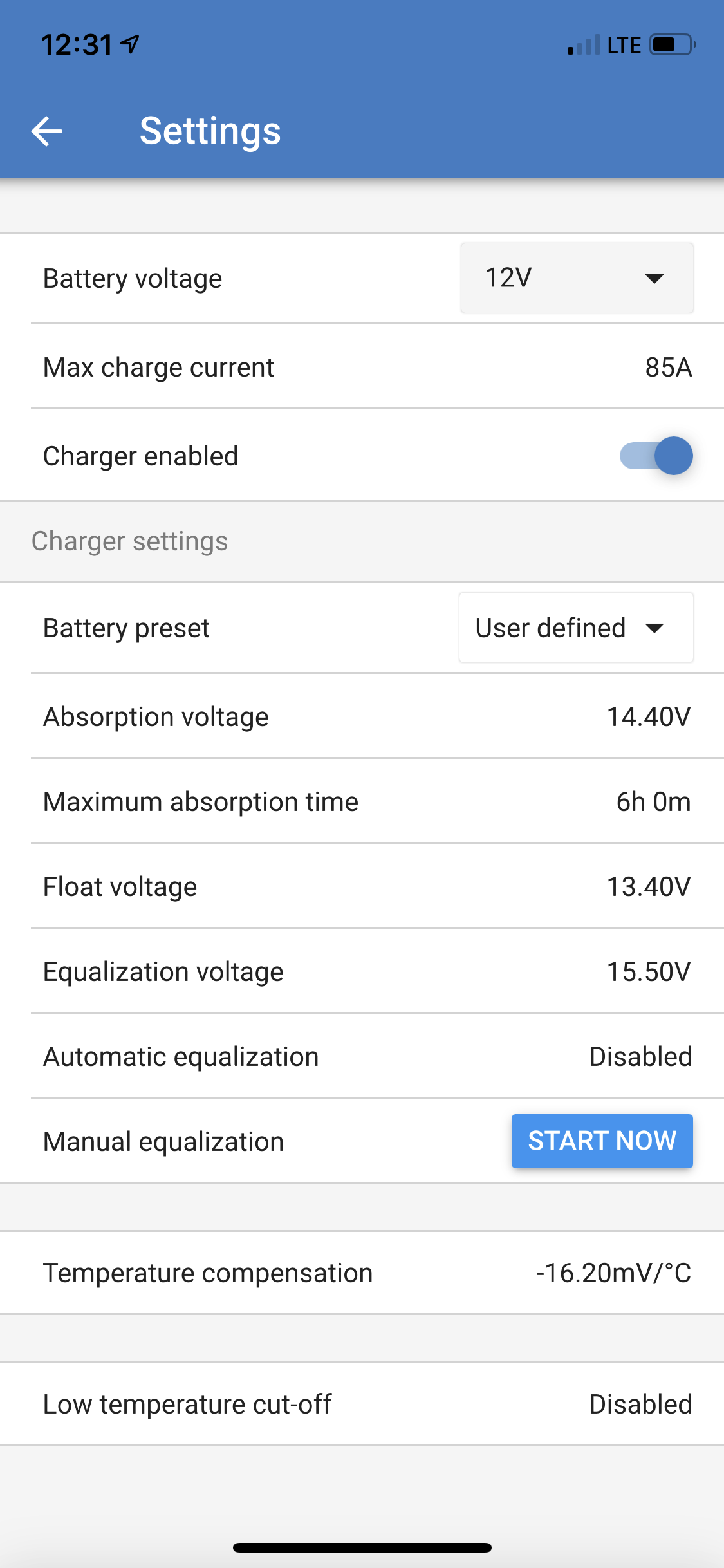
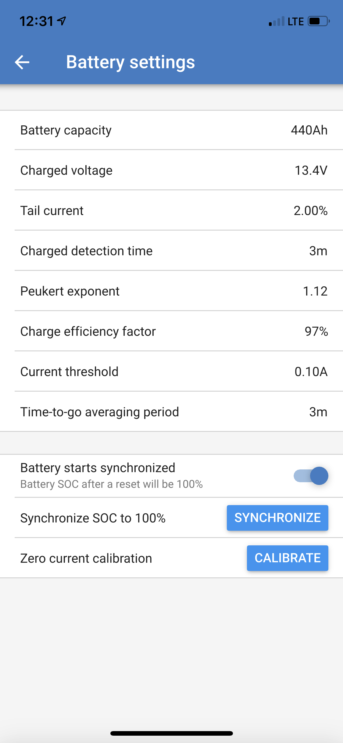
I have noticed that sometimes the SmartSolar continues to be putting in power to the batteries even after they have exceeded the 'charged voltage'. Why is this? The setting for 'charged voltage' in the BMV-712 is set at 13.4 (per LifeLine AGM manual). The settings in the SmartSolar MPPT are custom set to Absorption 14.4v, Float 13.4, Equalization 15.5v. I have the SmartSolar and BMV linked via Bluetooth.

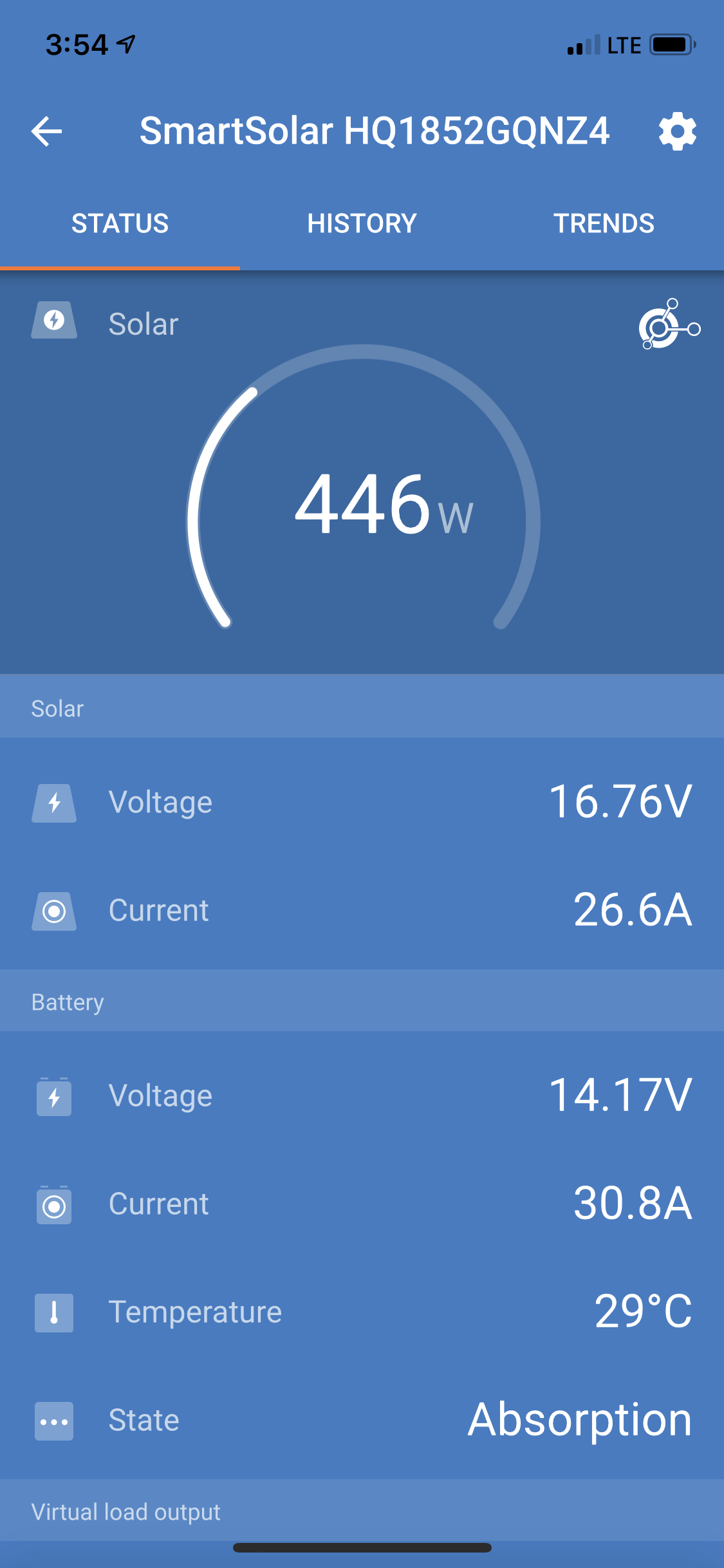
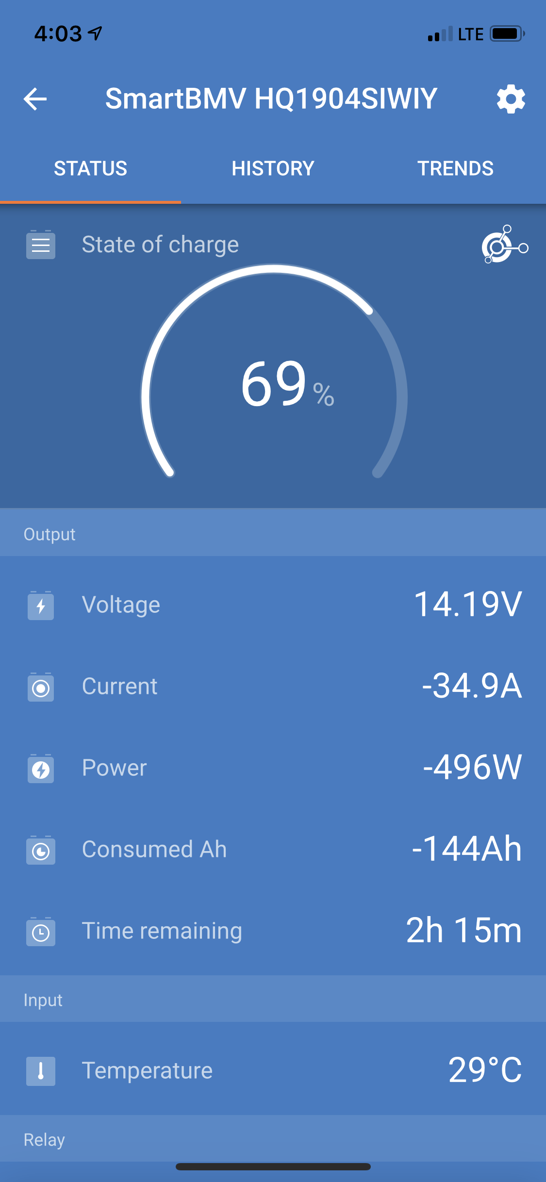
I'm attaching screenshots from the App on a day when it was really sunny and the battery voltage was up to 14.17/14.19v. Do I have a setting wrong? Thanks so much!
MPPT ControllersBMV Battery MonitorSOCVE.Smart Network
2 |3000

Up to 8 attachments (including images) can be used with a maximum of 190.8 MiB each and 286.6 MiB total.

1 Answer
Mark avatar image
Mark answered ·

The MPPT solar charge controller acts independently and is in full control of the charge cycle and charge voltages.

The BMV-712 only provides the MPPT with accurate battery voltage and battery temperature data to work with via the VE.Smart Network (via Bluetooth).

The absorption voltage set in the MPPT is 14.40V and the screen image shows that the MPPT is in absorption phase.

However, the configured voltage set-point is subject to temperature compensation (unless its deactivated) - at a battery temperature of 29°C and with a temperature compensation coefficient of 16.2mV/°C the corrected absorption voltage set-point would be 14.40V + (29-25)*-0.0162 = 14.33V. So ~14.3V is the TARGET that the MPPT is trying to maintain during the absorption phase.

The measured/actual voltage shown is ~14.2V which is very close, but I can also see in the BMV data that there must be a large load active at the same time, as the MPPT charge current is not enough to cover the load and charge the battery - there is a current draw of -34.9A from the battery and this would be pulling the battery voltage down a little.

The BMV 'charged voltage' setting is only one of the criteria required to 'synchronize' the BMV SOC reading to 100%. It does NOT change the charge state of the MPPT or communicate this information to it.

In solar applications it is generally better to set the BMV 'charged voltage' to the MPPT absorption voltage -0.2 to -0.4V. This helps to prevent false/premature synchronizations to 100% SOC due to fluctuating solar conditions/charge current.

14.4V is a typical absorption voltage for lead acid based batteries, but if your battery manufacturer recommends something different then you need to adjust this set-point in the MPPT configuration.

I would also recommend to check the battery manufacturers recommend temperature compensation coefficient, for most lead acid based batteries it's typically a little higher than the default ~24mV/°C to 30mV/°C (for a 12V battery/bank).

5 comments
2 |3000

Up to 8 attachments (including images) can be used with a maximum of 190.8 MiB each and 286.6 MiB total.

klim8skeptic avatar image klim8skeptic ♦ commented ·

Good answer :)

0 Likes 0 ·
Mark avatar image Mark ♦♦ klim8skeptic ♦ commented ·

Why thank you! :-)

0 Likes 0 ·
kshilanski avatar image kshilanski commented ·

Hi Mark,

Thanks so much for your answer! Thank you for taking the time to explain the set up as well. I have a few more questions perhaps you can help me with?

I now understand that the 'charged voltage' I put in the BMV of 13.4v is not shared with the SmartSolar. I'm guessing then that the charged voltage number then really only figures into state of charge calculations in BMV app.

But I'm having a hard time understanding if that info is not shared - how would the SmartSolar ever know when to stop putting energy in?

I could be wrong - but it seems like there are two voltages that are at play... the current voltage of the battery (I think this is called Open Circuit Voltage?), and the amount of voltage that the SmartSolar should be putting in.

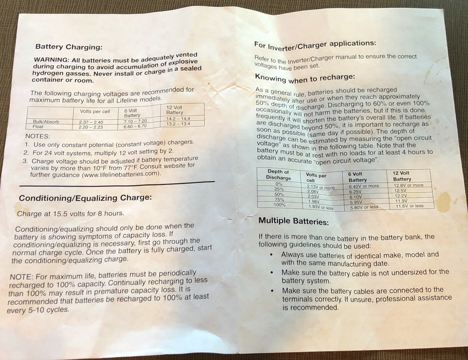
For example, if the voltage of the battery itself is 12.2v (which is 50% depth of discharge per the manual for our batteries), then it should be charged at Bulk/Absorption rate of 14.4v.

When the battery itself reaches 13.4v, it is full, and the charging should stop. I don't know how to make this happen with the app.

I'm having a hard time understanding why our batteries would still be in 'Absorption' state per the app when it's voltage is 14.17v.

Is 14.17v the voltage of the battery? or the voltage that is going into the battery? My guess is that it's the voltage of the battery because after we installed the set up we did some tests with a multi-meter and what we got there was the same as what was listed on the BMV and Smart Solar. So if the 14.17v listed on the App is indeed the voltage of the battery - it should not be in Absorption state.

Really the bottom line of my question is that I'm worried that with the current settings we'll be putting too much voltage into our batteries. And I'm not sure how to get the SmartSolar to work with the settings recommended by the manufacturer.

Also, the -34.9amps is going into the battery, not coming out in a load. I was really thrown off by the negative for a while as well, but after testing out a few things, when the BMV screen is showing negative it's amps being put in. So I don't know if I feel comfortable with being the reason it would be pulling the voltage down from the temperature compensated target of 14.3.

Thanks so much for taking the time to read my question and for any ideas you can offer!

I"m attaching a page of the battery manual for reference.

0 Likes 0 ·
Mark avatar image Mark ♦♦ kshilanski commented ·

Firstly, the BMV should display a POSITVE (+) number if current is flowing IN to the battery and a NEGATIVE (-) number if there is current flowign OUT of the battery. If you see the opposite then its likely that the negative battery cable connections to your shunt are back to front. Check that ONLY the battery negative is connected to the 'battery' side of the shunt and ALL negative cables from loads and chargers are connected to the 'load & charger' side of the shunt.

The BMV quick install guide is a good reference;

https://www.victronenergy.com/upload/documents/Quickinstallsheet_BMV70x_part1_2.pdf

Regarding the MPPT charge cycle, I can see in the spec sheet photo you provided that the recommended absorption voltage is 14.2 to 14.4v (for a 12v battery) and the recommended float voltage is 13.2-13.4v (for a 12v battery) - so your current MPPT charge settings of 14.4v for absorption and 13.4v for float seem fine.

AFTER you fix up your shunt wiring issue (assuming there is an issue), then you should monitor the current into the battery towards the end of the absorption phase, JUST BEFORE the charger switches from absorption to float. A good guide to tell if your battery is fully charged is when the charge CURRENT during absorption phase drops to <2% of your battery capacity - so <8.8A for a 440Ah battery bank.

However the MPPT doesn't know this information and the absorption time is controlled by the 'Maximum absorption TIME' that is configured - you currently have this set to 6h (which is reasonable).

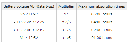
It's important to note that this is only a MAXIMUM time, and not typical of the absorption time during most charge cycles. The MPPT determines what absorption time to use based on the battery voltage in the morning just before it 'wakes up' and starts the charge cycle - by applying a FACTOR to the maximum time set.

See table below and the MPPT VictonConnect online manual;

https://www.victronenergy.com/live/victronconnect:mppt-solarchargers

For lead acid based batteries the charge cycle is such that it must;

1- First provide enough current raise the battery voltage up to the 'absorption voltage' set (with any corrections for temperature) - this is the BULK phase

2- Once the absorption voltage is reached the charger will then aim to MAINTAIN the absorption voltage and as the full battery capacity is slowly replenished the charge current will slowly decrease - this is the ABSORPTION phase

3- Ideally when the charge current drops below about 2% of the battery capacity the battery can be considered 'fully charged' and the target battery voltage can be lowered to the 'float voltage' - this is the FLOAT phase

I don't know what you mean by your statement that the battery is full when it reaches 13.4v - this is incorrect as its only the float voltage. It needs to be charged above that voltage level to be properly replenished, that's why the recommended absorption voltage is ~14.4v.

0 Likes 0 ·
1564642583621.png (15.4 KiB)
kshilanski avatar image kshilanski Mark ♦♦ commented ·

Hi Mark, Well I can't believe it's been so long - but I wanted to post an update. Thank you very much for taking the time to answer my questions. I'm still trying to figure out some of it, and I have a few new questions that I will post soon in the forum. But I wanted to post an update because I confirmed that our shunt had indeed been installed backwards. We had local 'solar experts' do the original install, but after reading your comments and finally looking into it today, we were able to confirm that it was backwards. My husband was able to install it the right way, and now we are getting positive numbers when current is flowing in and negative numbers when current is flowing out. Just wanted to say thanks, because it was your comment that helped us figure it out! Thanks!

0 Likes 0 ·

Related Resources

Additional resources still need to be added for this topic

MPPT Product Page

MPPT Error codes

MPPT 150/60 up to 250/70 Manual

Victron BMV battery monitors product page


Additional resources still need to be added for this topic

VE.Smart Networking Manual