I want to build a 48v system with my victron Lifepo4 batteries with victron ve bus bms.
How can I use a 3rd party inverter and charge controller?
This site is now in read-only archive mode. Please move all discussion, and create a new account at the new Victron Community site.
If you're not using a VE.Bus inverter-charger, no reason to use a VE.Bus BMS - just use a smallBMS and connect the rest of your system appropriately.
I already have the ve bus BMS. Just wondering how to connect it with a 3rd part BMS. İf not I'll have to get the small BMS. How does the small BMS cut off the inverter to prevent over discharge?
with Victron battery protector ( 48v 100 amp ) see Victron site product page for more
information
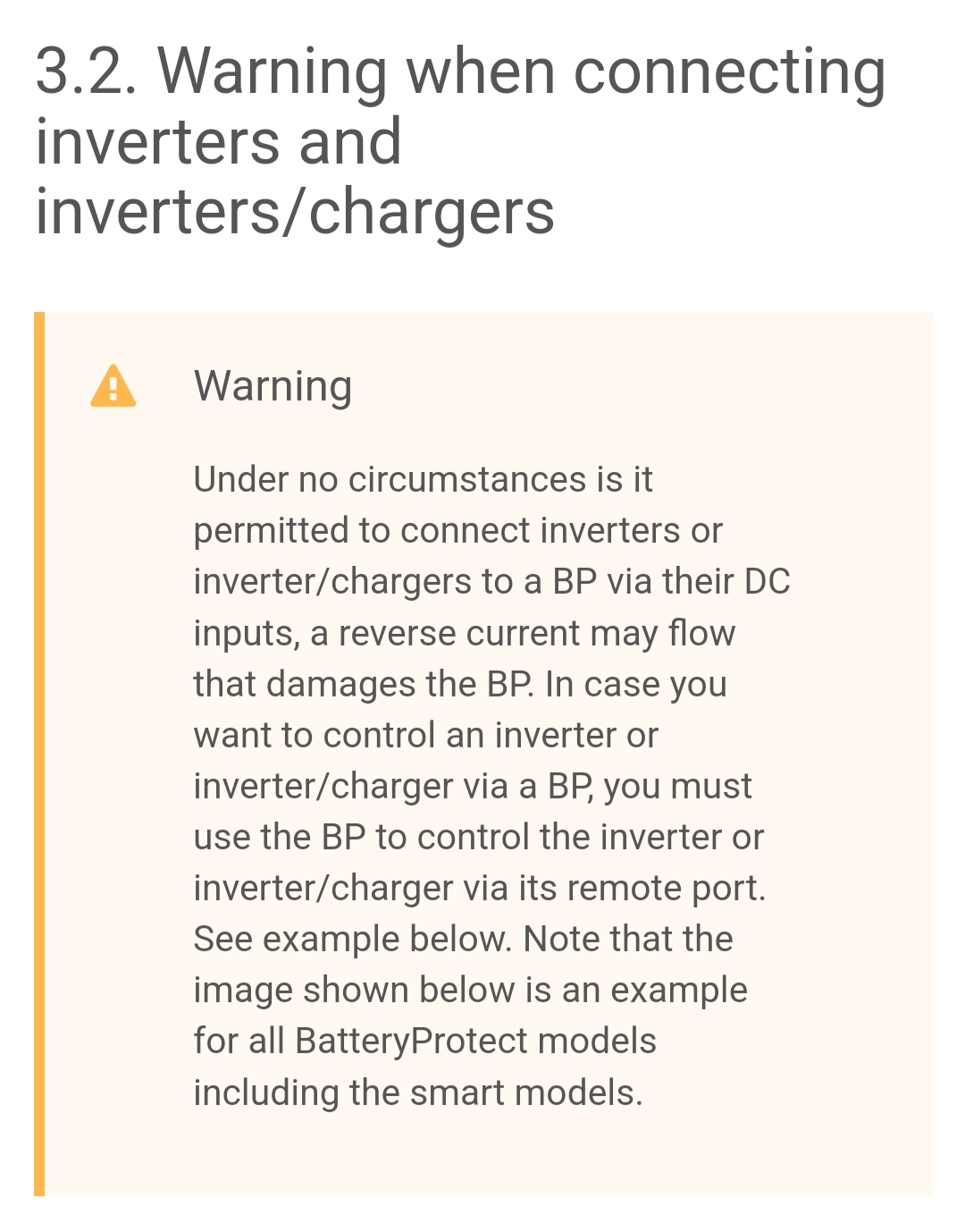
Don't use a BatteryProtect to switch an inverter!

This is a bit of a problem for 2 reasons.
1. Power
The VE.Bus BMS V2 needs to be connected to a VE Bus inverter or inverter/charger that is connected to the battery because the BMS gets the negative connection to the battery through the VE Bus cable. See section 3.2 in the manual for the VE Bus BMS Mk2. This does not apply to the original version (revised).
If you want to persevere with the VE Bus BMS V2 here is the VE bus pinout so you can see which pin is negative, which I believe is pin 3. Other people have managed to get the VE Bus BMS V2 working without the VE Bus cable connection, see the second link.
https://community.victronenergy.com/questions/64847/rj45-wires-used-by-vebus-pin-out.html
https://community.victronenergy.com/questions/206038/vebus-bms-v2-not-powering-up.html
2. Control
This will depend on your inverter/ charger which will need to be connected up using the ATC (allow to charge) and ATD (allow to discharge) terminals on the Ve Bus BMS. If your inverter/charger only has a single on/off input then this makes it difficult.
You'll need to study the user manuals of your 3rd-party inverter and charger to determine how to switch them from your Victron BMS. Since this is a Victron forum, we can't tell you much about non-Victron components or how best to control them - it's on you to read and understand the manuals for your chosen components.
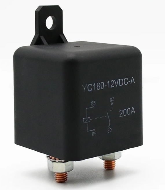
Can I use two of these to cut off the charge from the charger and load from the inverter?
Would it have to be a 48v or 60v relay?

Do not forget that the ATC and ATD outputs on the VE Bus BMS are low current, they are not designed for driving high power relays or contactors so you will need some form of intermediate relay. The ATC is very low current so you may need a solid state relay. Check the datasheet. You are using this well outside the expected conditions.
Coil Voltage 12 - 24Vdc 72Vdc 48 - 72Vdc
Voltage (Max.) 36Vdc 95Vdc 95Vdc
Pickup voltage (Max.) 9Vdc 48Vdc 32Vdc
Dropout voltage (Min.) 6Vdc 27Vdc 18Vdc
Inrush Current (Max.) 3.8A 0.7A (1.3A @ 48v )
Holding Current (Avg.) 0.13A@12Vdc / 0.07A@24Vdc 0.02A@72Vdc ( 0.03A@48Vdc )
Or... I could use a contactor to cut off the AC output on the inverter when the batteries are low. I'll just wire the relay into the load disconnect and have the relay switch the power going to the contactor. When load disconnect goes off then the relay would cut the power going to the contactor and switch off the AC output on the inverter. This would work right?
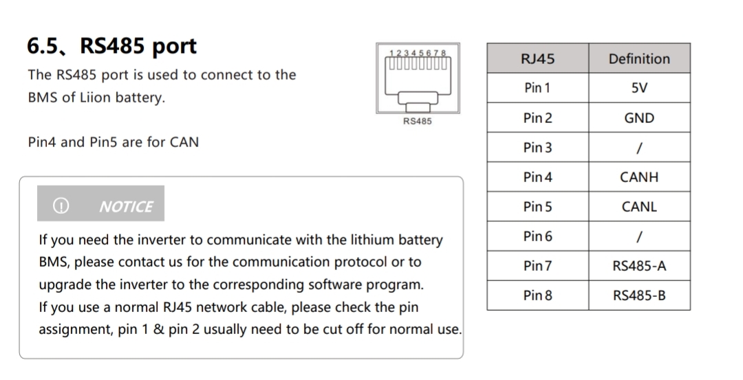
Pin layout on the new inverter. Can I make this work?
47 People are following this question.