question

fmueller87 avatar image
fmueller87 asked

RCD, Grounding Multiplus, Grounding Negative

Dear Community,

I am still learning so apologies if my question seems trivial. I have been reading wiring unlimited which is a fantastic resource, many thanks for that!

We are installing a Multiplus 1200 VA, and 2 x MPPT charge controllers. The Multiplus should prioritize Solar and Battery at all times, but it is connected to Grid in case batter SoC reaches 10% and there isnt sufficient solar available to recharge.

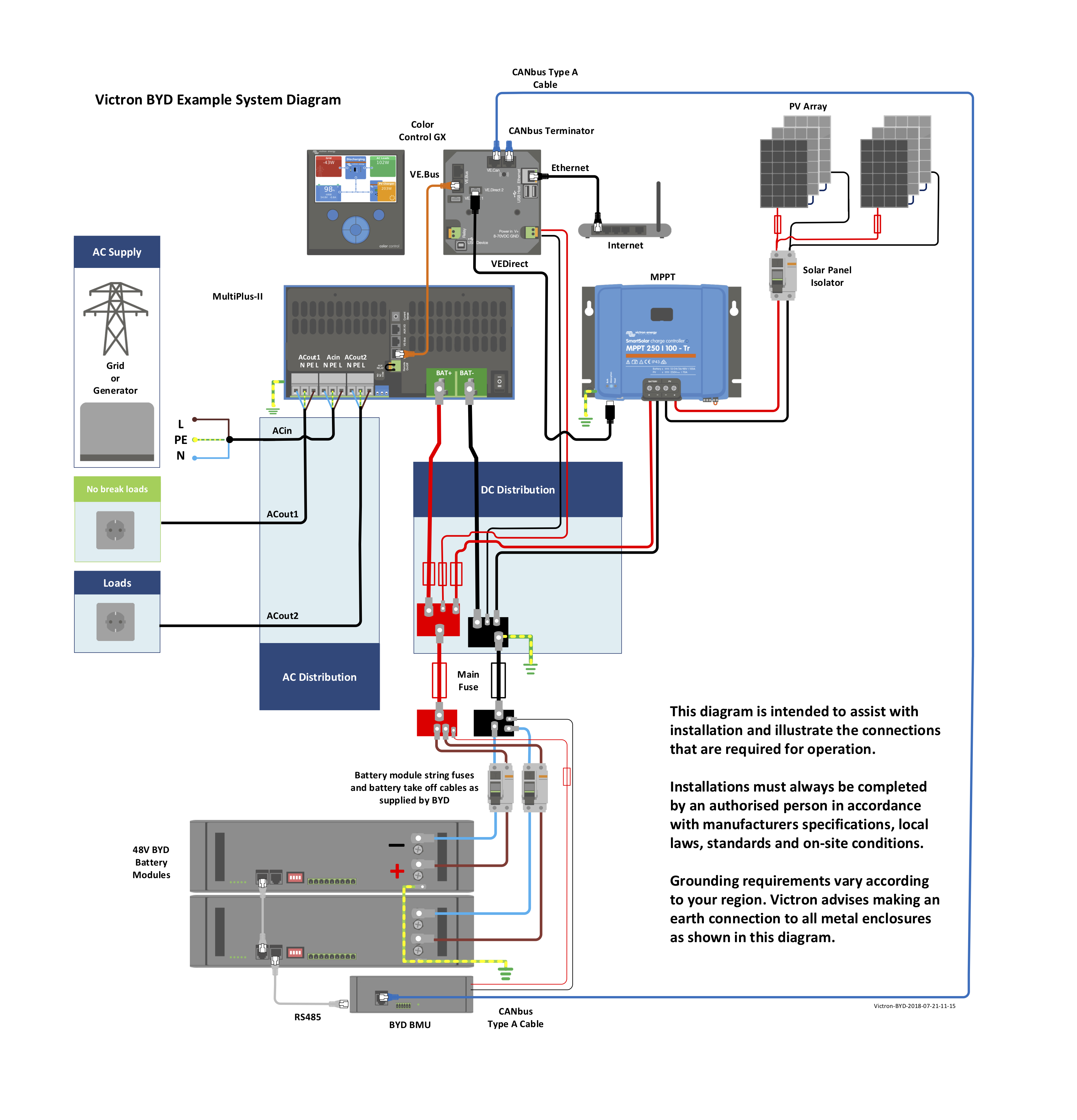
Question 1: In the BYD example diagram (shown), in wiring unlimited and several other sources, it is mentioned that the negative battery pole should be grounded. In this case the BYD battery has its own grounding point, is this just the casing, or is that the negative pole? Do I need to ground the negative pole in addition?

I am running my main battery cable through a 160 A NH breaker (rated for DC Voltage) and into a Lynx Distributor Busbar. Shall I ground the negative cable on the input side of the main fuse? Or there is an additional bolt point on the negative busbar of the lynx distributor, is this supposed to be grounded?


Question 2: Due to the system being "off-grid" but within grid vicinity, we are using the common building earth, to which the entire system (DC/AC/SOLAR Potential Earthing is connected). The input side of the Multiplus is protected with an RCD, the output should also be protected with an RCD, prior to the 2 x load MCBs that we wish to run?

A colleague mentioned that the RCD is so sensitive that it may be prone to nuisance tripping, suggesting to leave it out, is this the case? What do the experts recommend?

Does the Multi 1200 VA even connect the neutral to the ground when in inverter mode, like the larger models do?


Many thanks in advance for your help!!


Best regards


Fabian

MultiPlus Quattro Inverter ChargerinstallationGrounding
2 |3000

Up to 8 attachments (including images) can be used with a maximum of 190.8 MiB each and 286.6 MiB total.

2 Answers
Mark avatar image
Mark answered ·

You really need to consult a experienced & suitably qualified electrician (familiar with the local regulations) for proper guidance & confirmation on this complicated & potentially dangerous topic.

My thoughts (that you should confirm & interpret/use at your own risk) are:

1a- Only bond the battery negative to ground at one point, I would use the center bolt on the negative bus of the Lynx distributor and connect this to a main grounding busbar using a suitable cable (rated to the main DC fuse/circuit breaker current - so it could have the same cross section as the main battery cables)

1b- I expect that the ground connection point on the BYD battery is only for the case & not bonded to the battery negative (but you can do quick continuity check with a multi-meter), I would connect this to the main grounding busbar independently

2a- I would keep the building earth bus for the AC side only & connect it to the main grounding busbar via the main ground connection on the Multiplus unit (normally a M8 stud on the body)

2b- I would connect the PV ground & MPPT ground direct to the main grounding busbar

2c- You must only have ONE AC neutral-earth bond/link active at any one time and it must be located before (not after) an RCD for it to operate correctly (for all return current to pass through the neutral cable and balance with the current in the active cable - unless an earth leakage fault occurs)

2d- For non-fixed systems the 'grounding relay' within the Multiplus can be utilized to create a dynamic neutral-earth bond/link ONLY when no external supply is connected - as a neutral-earth link will commonly already exist in the external supply, but this should be confirmed (the Multiplus 'grounding relay' should be programmed as required for the setup)

3- You should only have ONE earthing point for the earth stake/rod/connection, I would also connect this to the main grounding busbar

1 comment
2 |3000

Up to 8 attachments (including images) can be used with a maximum of 190.8 MiB each and 286.6 MiB total.

sanchuka avatar image sanchuka commented ·
@Mark if you please can help me to understand grounding size cable, in your feedback no. 3.


In case of battery negative grounding and multiplus primary ground (chassis), information advice you to use same size that dc main cables as you suggest in no. 1a (or fuse rated).


But which cross-section you suggest for the one earthing point to stake/rod/connection from the main grounding busbar?


eg. Multiplus-II 48/5000 recommends 70mm2 dc main cables (assume also for chassis ground to grounding busbar), and should be also that cross section from main grounding busbar to stake/rod/connection?
0 Likes 0 ·
fmueller87 avatar image
fmueller87 answered ·

Many thanks @Mark on the extensive answer! Absolutely, a qualified electrician shall install it.

I am located in Oman and the incoming supply from transformer/feeder comes in as 4C cable (3 phases + Neutral), the Earth is established separately on the premises via grounding rod, earth grid, earth band in foundation etc. I believe this is a TT earthing system (Terre - Terre).

The inverter/charger will be configured to "ignore AC" if I am not mistaken, in order to prioritize the solar/battery setup, and will only charge if battery gets to 10% SoC. However, if the AC supply were to be physically disconnected, the inverter/charger will still be connected to the main grounding busbar. Is it desirable to have the 'grounding relay' activate, closing neutral to ground in the inverter/charger, although the inverter is still connected to the same earthing as the AC main busbar (through bonding)?

Reason I ask is, because the place that the Earth & Neutral are bonded in the supply side is in the transformer at star point. The 3 phases and neutral arrive at consumer switchboard and are kept separate from earth, the consumer earth is connected only to its respective earthing rod (As oposed to TN-C, or TN-C-S Systems (where Earth-Neutral are linked and split on coming into the consumer switchboard).

Either way I know that RCD/RCCB are used everywhere here.


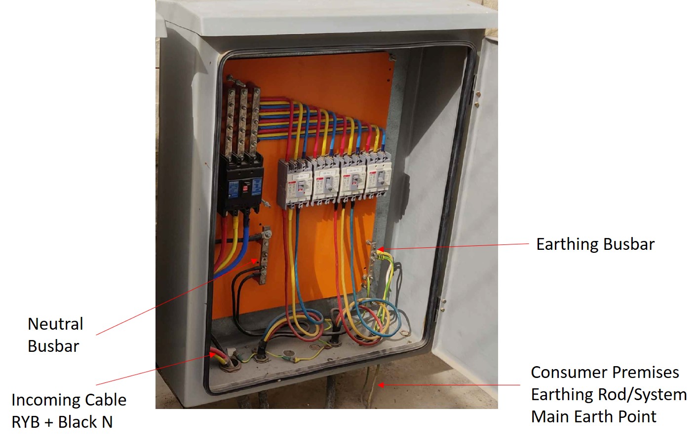
Below is a picture of the consumer DB where AC mains will be taken from and where main earth will be connected.


consumer-db.jpg (168.6 KiB)
1 comment
2 |3000

Up to 8 attachments (including images) can be used with a maximum of 190.8 MiB each and 286.6 MiB total.

Mark avatar image Mark ♦♦ commented ·

You need to refer to the manual for your particular Multiplus model to understand the operation logic (which may be different depending on the model), but when 'AC In' is ignored a dual pole relay should create an open circuit in the 'AC In' active & neutral, so any neutral to earth bond/link on the input side would have no effect.

Even when the intention is to not ignore 'AC In', but there is no power at 'AC In', the relay is in open circuit state until power is detected.

So in this case you would still require a neutral to earth bond/link to be created during this operating state - either temporarily using the Multiplus 'grounding relay' or by having a permanent bond/link after the Multiplus AC output & removing any other neutral to earth bonds/links currently in the system.

0 Likes 0 ·

Related Resources