question

vinopnw avatar image
vinopnw asked

Temp sensor with SmartShunt 500A IP65

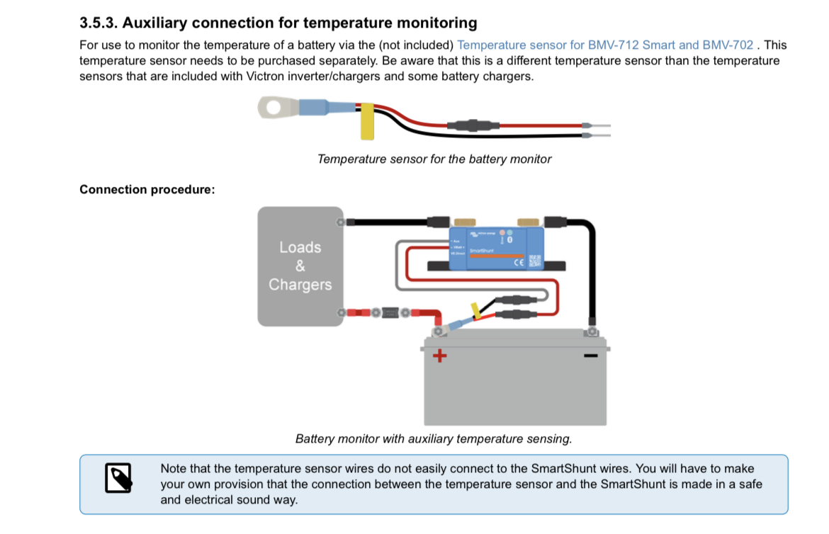
I’ve been trying to find information on the manuals and videos on how to I stall the temp sensor on the new smartshunt. I thought I would just replace the Vbatt + and Aux wires at the fuses, but the temp sensor only has a fuse on the red wire, not the black. The manual stated to use the ASS000100000 temp sensor, but that doesn’t seem correct. Where do I attach the sensor?img-0668.jpeg

image.jpg

SmartShunt
img-0668.jpeg (2.3 MiB)
image.jpg (3.9 MiB)
2 |3000

Up to 8 attachments (including images) can be used with a maximum of 190.8 MiB each and 286.6 MiB total.

6 Answers
pwfarnell avatar image
pwfarnell answered ·

Wire it up as per the manual with red to Vbat+ and black to aux. Why do you think the black wire needs fusing, it is not connected to the positive directly in this instance.

screenshot-20230622-082724-kindlephoto-2642788.png


2 |3000

Up to 8 attachments (including images) can be used with a maximum of 190.8 MiB each and 286.6 MiB total.

vinopnw avatar image
vinopnw answered ·

I don’t have the older version of the shunt where I can plug into the front. I have the IP65 version, where the Vbatt + and aux wires already exist in the unit and are epoxied into the side of the device


Edit:

Reading in the manual further, there is a note that the user has to make their own provision to connect the wires. It’d be great to have some guidance or examples about best methods to follow for the provisioning of the cable. For instance, where to buy parts, etc.img-0679.jpeg


img-0679.jpeg (258.3 KiB)
2 |3000

Up to 8 attachments (including images) can be used with a maximum of 190.8 MiB each and 286.6 MiB total.

vinopnw avatar image
vinopnw answered ·

I could go two separate ways.

1) I could simply cut the aux wire from the shunt and splice in the black wire from the sensor. I’d prefer not to modify the wires from the shunt, in case I want to change the functionality of the aux wire later. That was the reason I looked at the IP65 version versus the IP21 version.

2) I can install a fuse holder on the black wire from the sensor. But what fuse holder to buy that’s compatible with the existing fuse holders coming from the shunt wires?


I looked for videos showing how others have done their setup, but couldn’t find anything other than passing mentions to the temperature sensor in conjunction with the IP65 shunt

1 comment
2 |3000

Up to 8 attachments (including images) can be used with a maximum of 190.8 MiB each and 286.6 MiB total.

lundgrk1 avatar image lundgrk1 commented ·

I The fuse holder apears to be a Uxcell fuse holder: https://www.amazon.com/gp/product/B07SNB3BVJ/ref=ppx_yo_dt_b_asin_title_o00_s00?ie=UTF8&psc=1


0 Likes 0 ·
chrisj1952 avatar image
chrisj1952 answered ·

All electrical devices are comprised of electrical circuits (i.e the current effectively goes in a circle). So there is no need to put a fuse in both red and black wires, as they are in the same circuit.

Most electronics hobby retailers sell a length of wire with an inline 1A fuse holder, similar to those Victron fits to it's wires. So you can just splice them in.

2 |3000

Up to 8 attachments (including images) can be used with a maximum of 190.8 MiB each and 286.6 MiB total.

chrisj1952 avatar image
chrisj1952 answered ·

here's an example at Mouser Electronics


2 |3000

Up to 8 attachments (including images) can be used with a maximum of 190.8 MiB each and 286.6 MiB total.

cochese-187 avatar image
cochese-187 answered ·

All I know is whoever makes a YouTube video on setting this up will be YouTube rich going viral. I also have not found any good documentation instructions on proper utilization or temp sensor. I look forward to anyone postings to this as it's been a active thread.

2 |3000

Up to 8 attachments (including images) can be used with a maximum of 190.8 MiB each and 286.6 MiB total.