question

oet avatar image
oet asked

2 x Multiplus 2 in 2-phase ESS configuration on 230V IT (3-Phase Delta Norway)

Hi

I know that 3-Phase Delta is not supported. But what about using 2 inverters in a 2-phase configuration with 120 degrees shift? The goal is to be able to feed in more than the max 16A on a single phase limitation we have here in Norway, and still be able to control everything from one single Cerbo. I have no need for a real 3-phase network on the back side of the Multis. Some single phase critical load on one of them is basically enough. The second Multi should only act as a grid-tie inverter on a different phase to even out the power between the phases.


I got this drawing from a Norwegian Victron distributor. I assume it comes from Victron. I understood that this was somehow tested, and it works. There were some instabilities in the voltage on large load variations between L1 and L3, but except from that it worked. This setup may work in an non-ESS environment, since you can disable the N-PE ground relay. In ESS-mode you cannot disable the relay, and you will short L2 and L3 to PE on the output. The picture also states that "Ground/PE must not be joined"
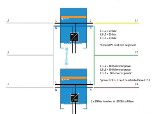
1674352921328.png


So what if we modify the above slightly to something like this:
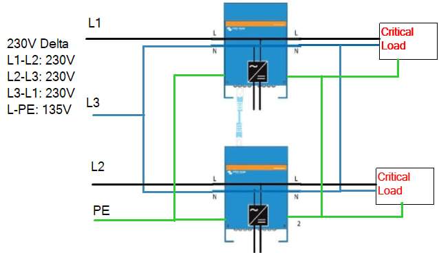
1674353326281.png

It is possible that the phase rotation will be wrong on the second unit. I'm not sure, but if we assume this is ok, this would allow ESS and feedback. In case of a grid failure, it will look like this:
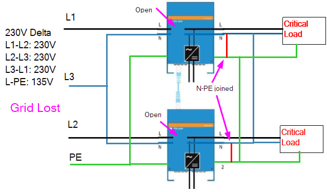
1674353517406.png

The internal relays will disconnect the inputs. The ground relay will kick in and join N and PE. Since we here have a common phase for N (the L3), this will not short out anything. It will create 2 separate single phase TN networks on the output. As long as you don't connect any load between the 2 inverters I cannot see that that is more problematic than running one single unit, which works fine.


Can anyone here confirm if above solution will work or not?

-Øystein

Multiplus-IIESS3 phasesplit phase
1674352921328.png (79.6 KiB)
1674353326281.png (88.8 KiB)
1674353517406.png (107.9 KiB)
1 comment
2 |3000

Up to 8 attachments (including images) can be used with a maximum of 190.8 MiB each and 286.6 MiB total.

Håkon Ingvaldsen avatar image Håkon Ingvaldsen commented ·

Løste du denne saken?


0 Likes 0 ·
8 Answers
s-forsberg avatar image
s-forsberg answered ·

You could check out these articles,

https://shop.pkys.com/Setting-up-parallel-and-split-phase-systems-using-the-Victron-MultiPlus-and-Quattro-inverter-chargers_b_161.html

https://community.victronenergy.com/questions/117864/it-grounding-system-with-quattro-230-v-4810000.html

https://community.victronenergy.com/questions/117864/it-grounding-system-with-quattro-230-v-4810000.html

https://community.victronenergy.com/questions/117864/it-grounding-system-with-quattro-230-v-4810000.html

And finally the Victron Vimeo channel is an excellent resource!

https://vimeo.com/user104980539


Regards

Sven

2 |3000

Up to 8 attachments (including images) can be used with a maximum of 190.8 MiB each and 286.6 MiB total.

oet avatar image
oet answered ·

Thanks for the links Sven.

However I cannot see that any of these directly answer my question. I think I have read all posts in the community related to this. Also I have watched the installer videos from Victron. As far as I can see my suggestion above will be the only design that will not short out anything when the ground relay closes. However I'm not sure if the MPs will reject the input since the phase rotation will be wrong. I know how to configure the above, (if it works). I'm looking for a confirmation if the design will work or not.

Using a 230/400 ΔY transformer is not something I want to do because of the losses.

-Øystein

2 |3000

Up to 8 attachments (including images) can be used with a maximum of 190.8 MiB each and 286.6 MiB total.

gerardg avatar image
gerardg answered ·

@oet hello.

I'm facing each day to that problem.

In Brussels, Belgium and Wallonia, a lot of house are connected in Delta... it's a nightmare.

Finally did you test your diagram?

It would be great and a good opportunity for Victron to help us in that problematic...

thanks a lot


Gerard

2 |3000

Up to 8 attachments (including images) can be used with a maximum of 190.8 MiB each and 286.6 MiB total.

Kristof G. avatar image
Kristof G. answered ·

yes, i am also very intressed !!!

if this works ( the pictures above ) , i will change my home to that.. can someone from Victron Team confirm this? @Guy Stewart (Victron Community Manager) , @mvader (Victron Energy)


here in belgium 3x240v ( without neutral ) is a nightmare to get an inverter that is 3phase and 48v


we need to find a solution to make Victron 3 phase work in Belgium :D


background info :


i have now (for my koi pond project ) used L1 and L2 for a grid connection to the Victron system and that is working fine for years .( on and off grid ) , ESS mode


house :

there is an inverter ( single phase ) on every L1-L2 / L1-L3 / L2-L3 and that is working fine too ... so why would the victron not work lilke that? ( i need to replace all the "old" inverters with a victron system :D )

1 comment
2 |3000

Up to 8 attachments (including images) can be used with a maximum of 190.8 MiB each and 286.6 MiB total.

Hi @Kristof G.,

Sorry I am not familiar with this configuration.

0 Likes 0 ·
janvi avatar image
janvi answered ·

My guess is, that this only works if you use 2 additional isolation transformers. Your 2nd schematic shows a dangerous voltage between PE and N what is not accepted by any RCD switches nor Schuko type wall sockets.

Multiplus already contains the torroid transfomer but this isolates from AC to DC and cannot isolate from AC in to AC out. With other words: The Multiplus works either as a charger or inverter but never both at same time.

Further I cannot understand the reason of the 3 phase delta without N. It does not allow any asymmetrical loads. Anyhow normal three phase transformer (ordinary transformer circuit Dy5 instead of 2 transformers with one phase) at the input will help in any case and produces the missing N of the delta and adapts the voltage to 230/400 Volt level what solves all problems.


2 |3000

Up to 8 attachments (including images) can be used with a maximum of 190.8 MiB each and 286.6 MiB total.

frankhe avatar image
frankhe answered ·

Addition. The neutral of every inverter needs to be referenced to ground for your installation to be ground referenced. Residual Current Detection devices only work when there is a reference to ground. A floating N-point is inherently unsafe and will kill you!

2 |3000

Up to 8 attachments (including images) can be used with a maximum of 190.8 MiB each and 286.6 MiB total.

frankhe avatar image
frankhe answered ·

I think there are two solutions here.

  1. you get three inverters with the N-point connected to ground. The voltage of the inverters has to be 133 V, 230 divided by the square root of 3.
  2. you get three inverters with the N-point connected to ground. The voltage of the inverters is 230 V. You need to convert your installation from 230 V line to 400 V line. You now have a system with a phase voltage of 230 V, between live and neutral. Get an autotransformer, three single phase transformers or one three phase transformer to convert your incoming supply from 230 V line to 400 V line.
2 |3000

Up to 8 attachments (including images) can be used with a maximum of 190.8 MiB each and 286.6 MiB total.

sharpener avatar image
sharpener answered ·

I think both solutions would work, at least in theory, but

#1. has the problem that it assumes the incoming 3-phase is perfectly symmetrical about earth. In reality I suspect it will float somewhat depending on how well the loads on the local grid are balanced. The inverters will try and correct this which may overload them as the source impedance will be very low. (In the UK which has 240/415V distribution you can usually measure several volts between the combined neutral/earth supply and true ground.)

#2. has the same issue if you use an autotransformer, so an isolating transformer would be better. A 3-phase isolating transformer for the whole house is unfortunately quite big and expensive. Also it would be an unusual way to wire a house and anyone working on it might not be aware of how it had been modified. I doubt it would comply with local regulations.

In either case am not sure how you would disconnect the system from the grid in a power cut, most countries require an approved anti-islanding device, this is built-in to Victron inverters but I am not sure it would work here. Edit: I think if you connect them with the transformer to AC-In and loads on AC-Out then it would detect loss-of-mains and work OK as an ESS in a power cut. The trafo will stay connected to the grid but this will not matter.

See also a similar thread here https://community.victronenergy.com/questions/25233/230v-without-neutral-in-belgium.html.

2 |3000

Up to 8 attachments (including images) can be used with a maximum of 190.8 MiB each and 286.6 MiB total.