Hi ,
I am getting a bit confused over my design and I wanted to get some help with a few questions . I hope someone with some expert knowledge could help me further ...
My current setup :
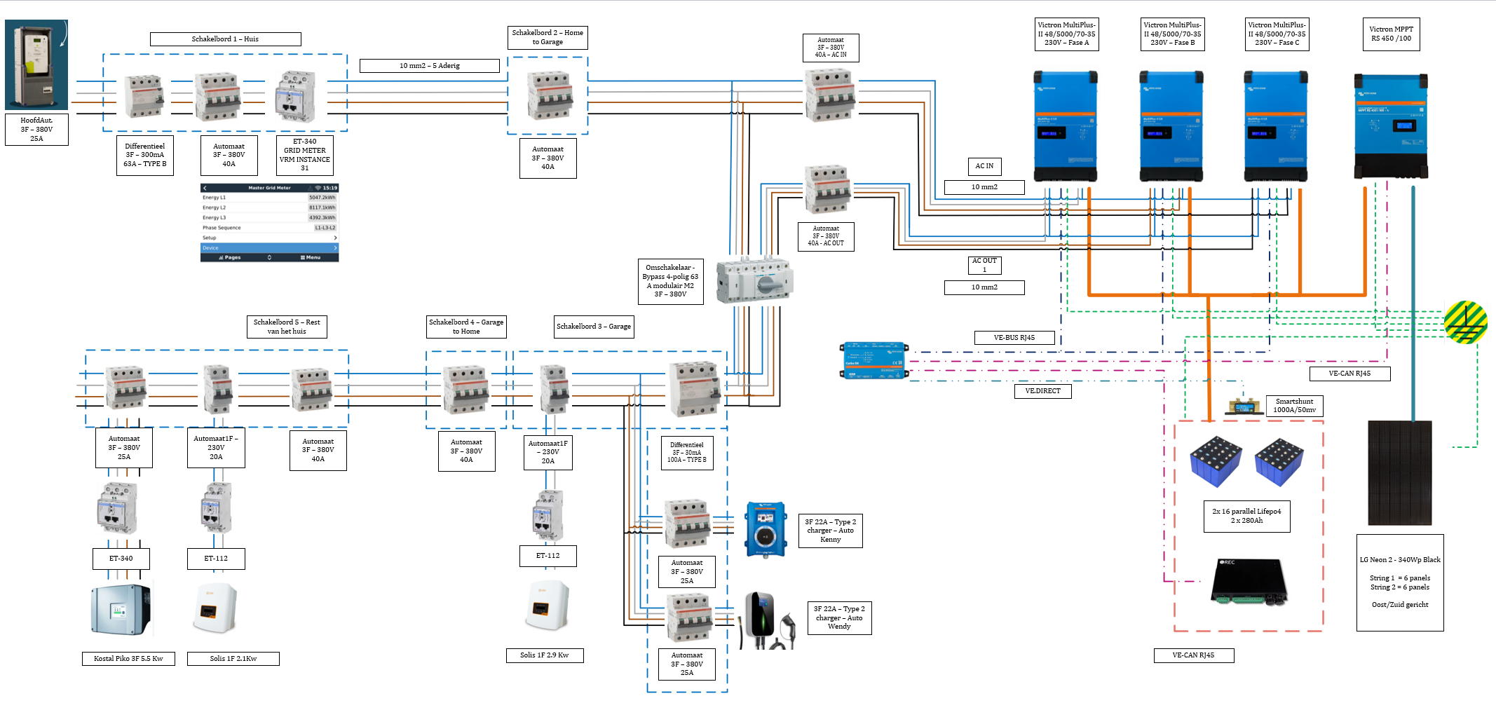
1. House AC IN has 3F+N (25A) + ET340 meter
2. 3 times Victron MultiPlus-II 48/5000/70-35 230V
3. 1x Victon MPPT RS450/100 for battery bank charge
4. 16 * (2x280Ah parallel lifepo4 cells 3.2v) - 48V battery bank with REC-BMS
5. 1x Victron smartshunt 1000A / 50mV
6. 1x Victron EV charger & 1x chinese brand EV charger on AC-OUT1 side
7. 1 x ET112 solar array 2.1KwP on AC-OUT1 Side
8. 1 x ET112 solar array 2.9KwP on AC-OUT1 Side
9. 1 x ET340 solar array 5.5KwP on AC-OUT1 Side
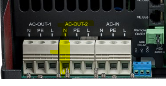
Question 1 : Somewhere in the manual of the Victron states that the neutral in a 3F setup of AC-OUT2 should always be connected. Can anyone explain me why if we do NOT use the AC-OUT2 at all.
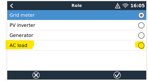
Question 2 : Should I add an additional ET340 with the setting AC LOAD right after the AC-OUT1 to measure the Current/Voltage created by the inverter ? This will lead me to question 3 ...
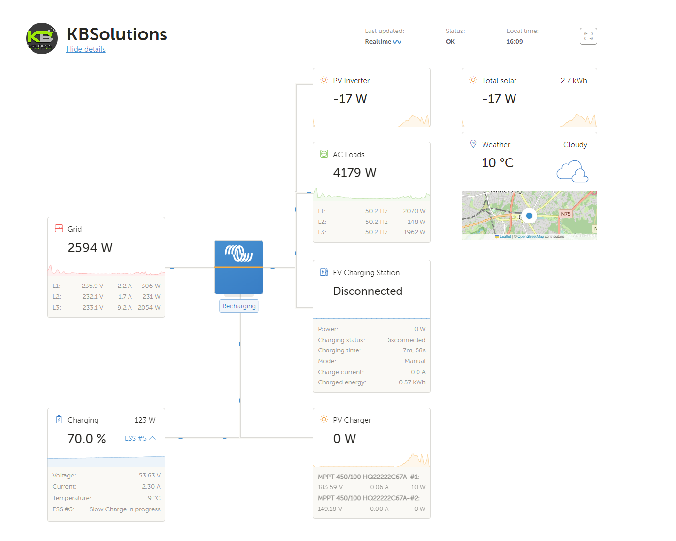
Question 3 : When I look at my dashboad I see wrong numbers (I think) .. What can be wrong :
- Case 1 and Set with following settings below : 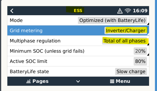
I have this dashboard with following readings ... AC LOADS are not representing Grid load (should be more or less equal as charging battery slowly)
-Case 2 and Set with following settings below :
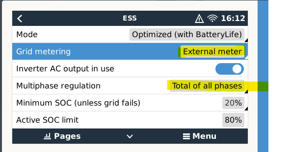
Then I have this dashboard with following readings ... Why do I have critical loads connected ? As none of my AC-OUT2 loads are connected ( only the neutral cable as per question 1)
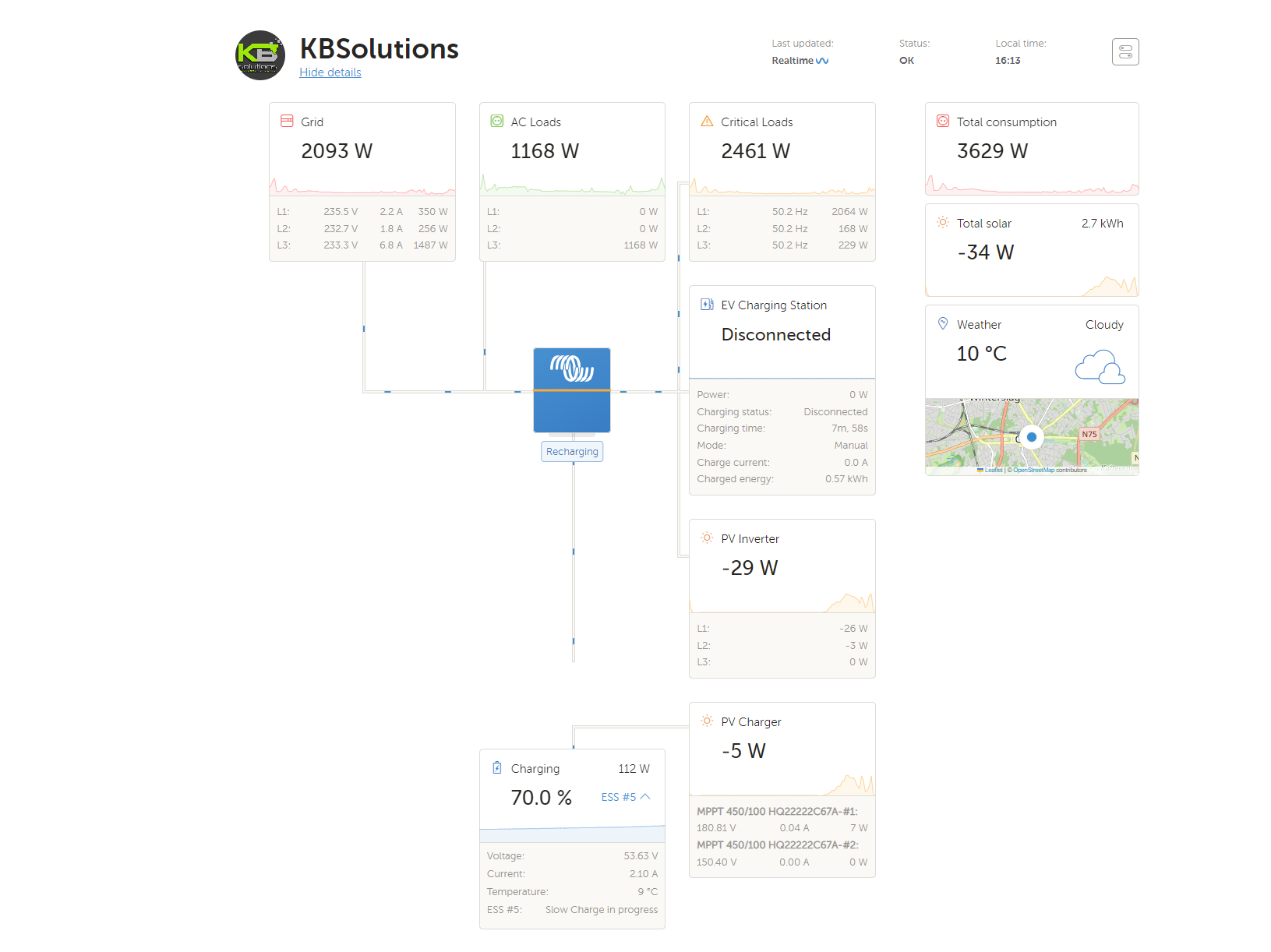
I am getting crazy on question 3 as I don't know what I am doing wrong here ...Or maybe I interpreted it wrong .Would be good if someone could help me out here to understand the issue
Thank you
Kenny

