question

Craig Chamberlain avatar image
Craig Chamberlain asked

Multiplus-II 48/5000 ESS with external grid CT & ET112 on critical loads

Hi,

I have an ESS setup where the original consumer unit has been replaced with a primary CU to serve non-maintained loads such as electric shower, range cooker, EV charger and the Multiplus-II 48/5000 via AC-In. I then have a secondary CU, powered from AC-Out1 which serves all the other house loads as maintained loads.

I have a Victron external CT clamp around the main meter tails to sense grid power, mainly because I know this is the best way to get fast response to ramp up/down and therefore to maintain a given grid set point.

This setup works fine but on the VRM dashboard and remote console I only see a single value for "AC Loads" which is a combination of the loads from the primary and secondary CUs. What I would like to see is separate values for unmaintained and maintained loads.

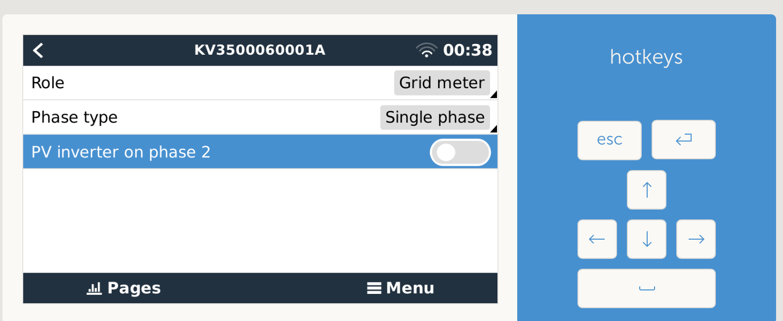
So, I decided to add an ET112 inside the secondary consumer unit to measure the maintained loads directly, expecting that this would show up in VRM and the console but it doesn't. This is probably because I have the ET112 set to the "AC load" role which it says in the Cerbo GX manual is only for monitoring purposes. I can read the data from the ET112 via the advanced section in VRM and it's still useful to be able to do that but would be much better if I could see the loads split graphically in the main dashboard or console.

I'm pretty sure I could get it to work the way I want by ditching the external CT clamp and moving the ET112 to the primary CU but then I'd lose the fast response of the grid set point.

Any other way I can get this working the way I want? Any chance Victron's software team might make this topology a supported option to discriminate between maintained and unmaintained loads in the user interface?

Many thanks, Craig.

Multiplus-IIEnergy Meter
2 |3000

Up to 8 attachments (including images) can be used with a maximum of 190.8 MiB each and 286.6 MiB total.

2 Answers
sharpener avatar image
sharpener answered ·

AIUI you don't need a meter on the maintained loads on AC-Out 1 as the Multi has an internal sensor for this.

I don't understand how you are getting <a single value for "AC Loads" which is a combination of the loads from the primary and secondary Customer>, as how is it measuring the non-maintained loads on the AC-In? Unless the Multi sees the reading from the external sensor is different from the internal sensor and deduces the existence of the loads. AFAIR plugging in the external sensor used to disconnect the internal one, but recent models have a connection to a terminal block instead.

Have you tried putting the ET112 on these loads, and in Settings|Energy Meters list it as AC meter on AC-In1? That might work or at least lead you towards a solution.

1 comment
2 |3000

Up to 8 attachments (including images) can be used with a maximum of 190.8 MiB each and 286.6 MiB total.

Craig Chamberlain avatar image Craig Chamberlain commented ·

Hi @sharpener , sorry there was a typo in that line where "Customer" should have said "CUs" (ie. Consumer Units). Fixed in the original question now.

Firstly, I'm not using AC-Out2 so let's ignore it for this discussion.

From what I understand the MP2 has two internal current sensors, one on AC-In and another within the inverter core module which effectively measures power to and from the battery. So if using the internal CT on AC-In then you can say that P(AC-In) = P(AC-Out1) + P(Inverter).

However, in my case I am not using the internal CT and instead I'm using the external CT attached to my main meter tails with a set of high load circuits being fed from my primary CU upstream of the MP2.

And, when using the external CT, the internal CT is disconnected so the MP2 has no way to know how much of the grid power went into my EV/shower/cooker and how much went straight through to AC-Out1. All the MP2 knows is that power is flowing through the external CT but it can't tell how much of that is flowing through AC-Out1. What I believe it does in this case is derive the "AC Loads" power value by taking total grid power and subtracting the inverter power (during charging for example)

So what I've done is add an ET112 as the first device inside the secondary CU and then all my RCBOs are fed from that via the main switch. This at least lets me see the power flowing in my secondary CU albeit I can only see that in the advanced view.

Worked example to illustrate:

Total Grid Import. (Ext CT) 10kW
Battery Charging (Inverter CT) 2kW
"AC Loads" (Calculated) 8kW
above comprised of
EV Charger on Pri CU 7kW
Maintained loads on Sec CU (ET112) 1kW

So without measuring the maintained loads CU directly there is no way that I can see to separate the maintained and unmaintained load figures when using an external CT. This does actually work but like I said only in the advanced view.

Now if the grid failed and AC-Out1 was being powered entirely from the battery/inverter then yes the ET112 would become redundant at that point because the inverter internal CT would be measuring the output. Although, that said I wonder if the inverter will measure power out before or after efficiency losses so conceivably we might find that my ET112 measures about 96% of the level reported internally by the MP2.

Anyway, apologies if I'm not explaining, or perhaps not understanding this very well. But hopefully the above helps to understand my perceived problem at least.

Thanks.

Clarification: I have one of the newer MP2s with the terminal block for the CT sensor but you have to remove a link wire when installing the external CT and so the internal one is still being disconnected. There is a setting in VE Configure 3 to tell the MP2 that an external CT is connected because otherwise it can't tell.

0 Likes 0 ·
jameswest avatar image
jameswest answered ·

Hi Craig,

Did you ever get an answer to this? I'm in a similar situation and was thinking of replacing the ET112 on the grid input with an EM530. This reduces the response time down from 750ms to 100ms. And you won't need to use an external CT clamp from the multiplus, so that can be used to monitor your critical loads.

I believe the EM530 has the added advantage of being able to monitor a 2nd load in single phase installations and display that on the Cerbo GX.

6 comments
2 |3000

Up to 8 attachments (including images) can be used with a maximum of 190.8 MiB each and 286.6 MiB total.

dansonamission avatar image dansonamission commented ·
Go to settings, ESS and turn on Inverter Ac output in use. This will show on VRM.
0 Likes 0 ·
Craig Chamberlain avatar image Craig Chamberlain commented ·
Hi @jameswest , no unfortunately I didn’t really make any progress on this but I like the idea of your suggested solution and will certainly look into it. Is the EM530 officially supported for use on a single phase MP2? How many consumer unit slots does it take up? From the spec it looks like three but not 100% sure.


My primary concern initially was reducing export to an absolute minimum but now I have formal approval from my DNO to export up to 4.4kW I’m less concerned with this and considered just installing the ET112 as a grid meter and accept the slow response. But if there is a faster meter then that would definitely be a better option. I could repurpose my existing ET112 to monitor my EV charger circuit to get better stats on that.


Let me know how you get on if you decide to get an EM530. Thanks.

0 Likes 0 ·
ejrossouw avatar image ejrossouw Craig Chamberlain commented ·

3 slots and the EM540 is the one Victron recently added to their list, I have an EM530 with an external CT on my testbench and the GX is fine with it.

1681429177478.png

1 Like 1 ·
1681429177478.png (89.6 KiB)
jameswest avatar image jameswest Craig Chamberlain commented ·
Yes it does take up 3 slots but am unsure about official support. It’s certainly supported in 3 phase environments but I’m interested in single phase. I suspect it’ll be a case of give it a try and see what happens.
0 Likes 0 ·
ejrossouw avatar image ejrossouw commented ·

@jameswest EM530: Class 0.5S (kWh), class 2 (kvarh). Current inputs via 5A current transformers (max primary current 10,000A) Are you thinking of the EM540 maybe?


0 Likes 0 ·
jameswest avatar image jameswest ejrossouw commented ·
The EM540 only works up to 65A per phase. I’m looking to try the EM530 in a 100A single phase environment to see if get better performance over the ET/EM112.
0 Likes 0 ·