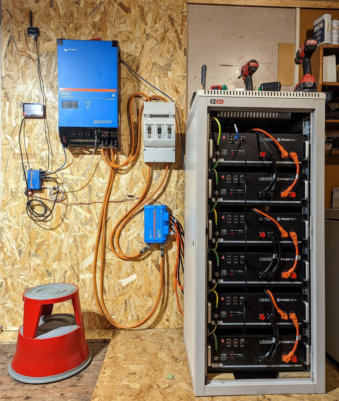
I have a Multiplus II 10kv and a Pylontech battery stack (A/C yet to be hooked up):

This is for time-shifting grid-connected energy storage.
I bought this as a kit from Bimble Solar in the UK. The DC cables between the Lynx Distributor and Multiplus are pre-made. I don't have a crimping tool, so had to arrange the setup within the constrains of the provided cables.
For a setup of this size, the Victron recommendation was for pairs of 50mm cables for positive and neutral connections between Lynx distributor and MultiPlus, and a 400A fuse on for DC side. Pylontech 25mm extension cables were used for pairs of the US5000s, resulting in three connections into the Lynx distributor, each with a 125A fuse.
Due to supply constraints, instead of a ANL 400A fuse and a DC isolator as originally planned, this was replaced with a Mersen Multibloc Fuse/Isolator. A 400A fuse was provided for each of the two positive 50mm cable connections.
1) Two 400A fuses seems wrong. As these are arranged in parallel shouldn't these should be twin 200A fuses to meet the 400A requirement?
2) I understand the recommendation is for a 400A fuse between MultiPlus and batteries, and that this is more to protect the cabling than the equipment, but as the three 125A fuses in parallel are below this rating, couldn't I could get away without the Mersen fuse/isolator altogether and instead simply have a 400A rated Isolation switch?
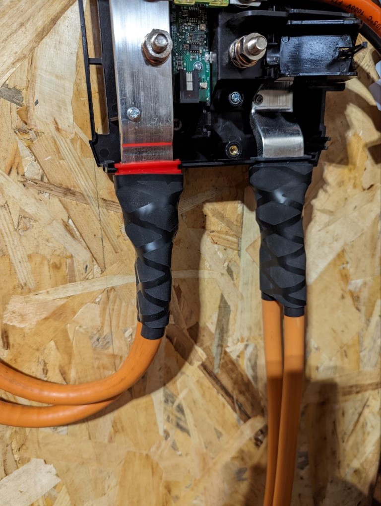
3) The use of twin 50mm cables from the distributor is awkward/impossible to stack and fit into the recessed +/- connections of the Lynx. I therefore had to place them either side of the external connections of the Lynx. As these connections are now somewhat exposed I plan to cover with very large diameter heat shrink tubing. Any suggestions for how I might get the pairs of these 50mm cables to fit into the recessed connections and/or better way to cover the exposed external connections?
4) Any other comments/observations/recommendations on the setup as described?
Thanks, Paul.

