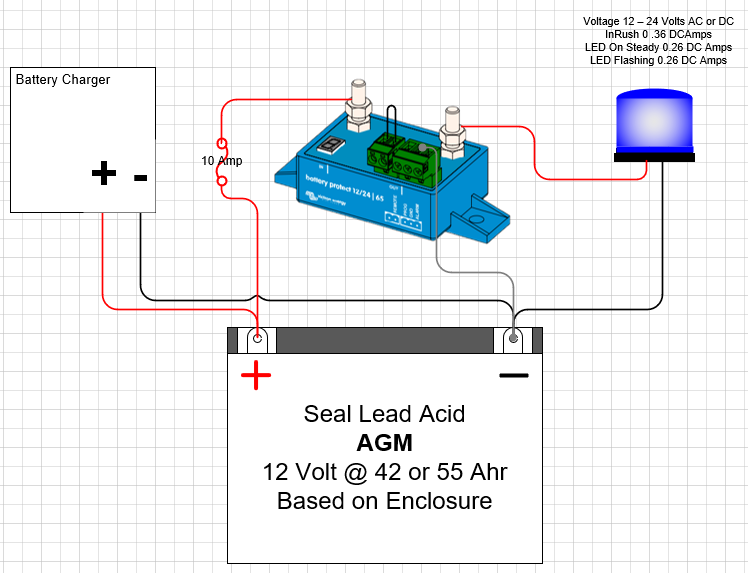
Hoping someone can help understand what should be a simple LVD device.
I'm new to the BP series, and I find my self confused by some of the instructions. This is due to the face I've received and E1 code indicating short circuit, and my Output is never enabled.
Installation Step 4: SC will be activated when connecting directly to loads with a capacitors on their input. The light I'm connecting to has wide voltage range. 12 - 24 Volts AC or DC. That seems to make sense. However the lights In rush is 0.36amps with a nominal draw of 0.26 amps.
Clearly this light has capacitors due to the onboard power supply. but the current is less than 0.5 amps.
Instruction online talk about placing a 10k resistor in pin 2-1, (which is not labeled on the device) placing a 10kΩ between P2-1 & 2.2 didn't have a positive affect. (None of the BP-65 images have any labelling for the 2 pin plug other than "Remote")
When I connect my Fluke meter in DC voltage mode, and connect to the Programmable DC source (I'm using to test with), I only receive a 12V reading when I plug in the default remote jumper plug. If I lower the voltage to 9 volts (set to number 8 in the table), the BP-65 never disconnects the load automatically. I have to unplug the remote jumper plug. Again confusing me to no end.
Image of my simple test configuration is attached
