Hi,
Im using the victron lynx shunt with a 3pase system (48/8000).
But the smartshunt voltage readint is 0,5V!!! To low.
is there a possibility to adjust or do i have to replace the shunt?
- Home
- Anonymous
- Sign in
- Create
- Spaces
- Grafana
- Node-Red
- Unsupported topics
- Questions & Answers
- Modifications
- Communauté francophone
- Deutschsprachiger Bereich
- Preguntas en Español
- Explore
- Topics
- Questions
- Ideas
- Articles
- Badges
question
Lynx Shunt wrong Voltage value
Hi Michael,
I have pretty similar problem - my lynx shunt shows about 200mV too low voltage without any load.
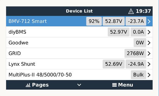
I have connected bmv-712 in series with lynx shunt and it shows almost exactly the same voltage as bms (about 10mV voltage drop).
When the load is connected then the voltage drop is about 100mV on bmv and 300mV on lynx shunt so the reading error seems to be consistent.
So it looks like that there is calibration issue. Have you find out how to calibrate this shunt?
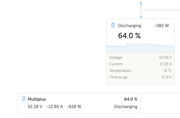
Below you can see my radings.
Is your system on and working?
If you run through the commissioning check you may spot something.
Are there any error lights/ reported conditions on the GX?
I had a CNL fuse in mine and it was also as accurate as a weatherman on acid.
Got a new LYNX Shunt. but also nearly 0,5V to low!!!!
Maybe a Victron specialist has an answer?
I have the same problem. Lynx Shunt shows about 0,15v lower voltage than my multimeter and multipluses. If I charge to 56,2V then I have to set fully charged voltage in Lynx shunt to 56,0V so it can calibrate it to 100% when fully charged.
There is a reason why it is callled the art of electronics npt the science of electronics.
The variation you see is considered acceptable.
Look up DMM accuracy and precision articles like this one, and there is also a neat one from Fluke.
Digital meter reading can be affected by temperature, not just its current temperature but of the meter was ever left in the sun it can be negatively affected. how long since its last calibration etc.
Most battery manufacturers sort of acknowledge this by giving 0.3v of a range for battery charging... For example float 13.5 to 13.8v...
Comparing to the DC bus voltage of the inverter is not accurate either as power is passing over the terminals and that can affect voltages. The way it is connected in the system can affect reading. Especially if the mppt was directly connected there to the battery terminals, or they are closer on the bus bar than the battery.
Here is one as well...
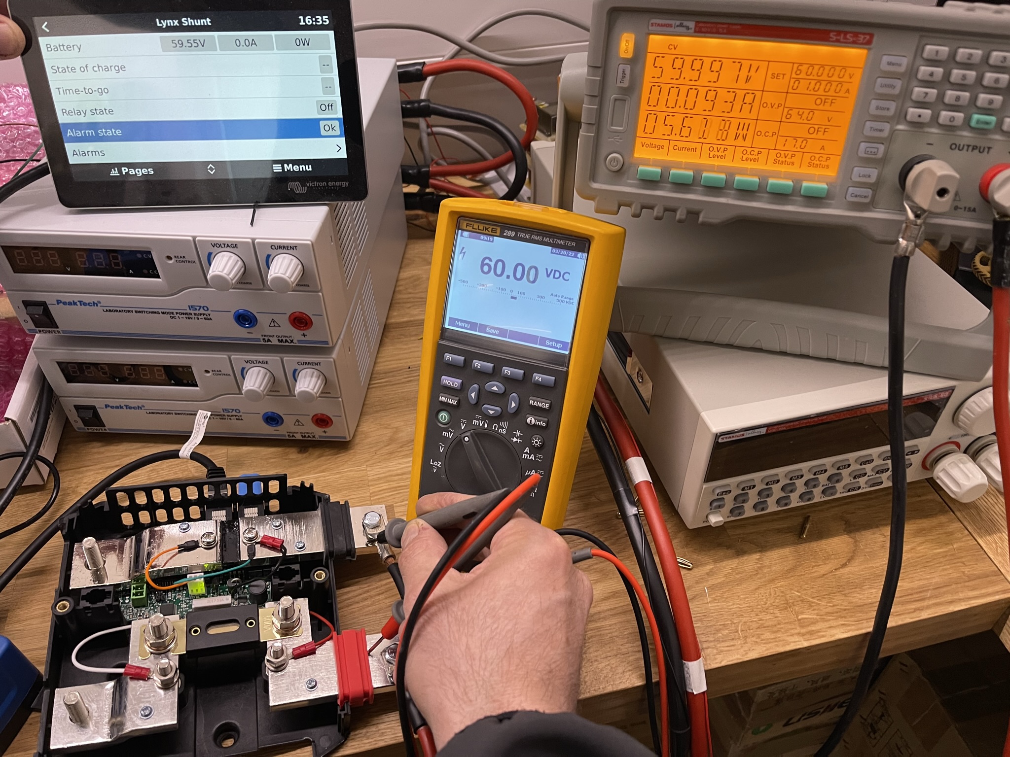
My 4 MPPTs are showing Voltage with +/- 10mV difference between MPPTs which is good. My Fluke (very well calibtrated) shows 7mV more then MPPTs.
Unfortunately Lynx Smart Shunt VE.can shows apx. 200mV less then MPPTs and Fluke wich is not good.
My BMS shows +/- 50mV from MPPTs
I was uncertain about wiring and checked cables etc. but no difference.
Earthing is OK as well.
I changed DVCC SVS setting to (is recommended to set to ON with shunt) off but it has no effect on any voltage.
@Alexandra - Im not sure if this is normal but I would say if Victron can produce MPPTS with that accuracy they shoud be able to do the same with Smart shunt as well, specially because it is used as refference point and can not be replaced.
The mppt also has a voltage potential from the panels. So can read higher.
And the way a shunt measurement system works is to measure voltage drop over itself. By default it is a resistor in the circuit. That resistance is usually a configured vakue as well. Which is why it can be changed on the BMVs. So you can use a different shunt with its board.
See this article.
With the added resistance in crimps and connectors there will be reading difference from current sources and current drains. And then the allowance for components to be of different tolerances.
If you even look up a simple resistor you will see some can be 5% out. Solar panels have specification tolerances of 3to5% depending on the brand.
At the end of the day electronics and electrical engineering is not an exact science.
Yes, shunt is resistor but BMVxxx with different shunts have 50mV voltage drop not 200+mV that is way to much. On the other hand, if that is by design to have that large voltage drop for some reason, it shoud be compensated at read out value.
Further more, when DVCC/SVS is ON, it should synchronize voltages thrueout the system, right?
Hello,
here is another one: test setup without load and so far without solar panels:
2x 14kWh battery with JKBMS, 3-phase Multiplus 3000, 2x MPPT 250/60 - batterys full/idle and well balanced, environment at 17°C w/o sunlight, all components reporting 54,00V +-10mV - just the Lynx smart shunt reports 300mV less.
Any ideas?
Regards,
Michael
Hi again,
I updated my MPPTs today to fw. v3.13, I think, but I could not notice that it made any change about voltage readout. Some hour or so later, I was doing some reconfiguration of my 3-phase multies and decided to do it from scretch by reseting all settings to factory defaults, made my setup and uploaded configuration to units. I didn't notice imedeately but after some time I realised that my voltage reedings are almost identilcal (+/- 10mV) on all devices, MPPTs, Multies, Lynx shunt, VE-bus etc... They all now show LYNX value which is about 150mV lower than real voltage measured with instrumet. I checked logs and could see that this change came instantly after booting multies and no other settings were involved. Interesting right?
BTW, I got new Lynx Shunt from Victron as replacement for first one which was 250mV off.
New one was off too, about 150mV untill this reset. multis are on fw v500.
I would not say this is solution but in some way it is better to have same value on all devices even slightly wrong, but it is the same... it is easier to compensate for difference.
Same issue here. Lynx shunt reports about 0.3v lower than 2 different multimeters. This causes issues (high voltage) with charging on default voltages. So I have changed the settings, but it is a bit annoying. This also occurs with no load/charging.
You're not alone. My Multiplus reads almost exactly the same voltage as my BMS yet the Lynx Shunt is way off.

I've an old smart shunt in a small system in the shed, i'm tempted to steal that and add it to my system, as another annoyance besides the inaccuracy is the Lynx Shunt is does not show the SOC past the first decimal point, yet the Smart Shunt does. Other than it being aesthetically more appealing and the addition of a fuse holder it seems to be seriously lacking and inferior to the Smart Shunt despite the hefty price tag.
Does anyone have a solution for this other than disconnect the Lynx Shunt and fit a Smart Shunt?
Hi all!
On Youtube (Victron Energy Channel) there is a video series about the Lynx System:
https://www.youtube.com/watch?v=OWJvDYDkl5E&t=35s
So i asked in the comments:
Is it possible to calibrate the voltage of the Lynx Shunt? The voltage reading is 300mV too low. There are threads in the Victron Community Forum reporting this issue but no solution. Voltage measurement done with Benning MM7-2 (0,03% + 2 Digit; 60000 count).
Johannes Boonstra answered:
No its not, make sure the connection to the battery (inline fuse and such) are as loss free as possible.
I assume this thread can be closed now.
I have the same issue. I'm considering using the V sense of the Multiplus directly to the battery terminals and use that as the reference voltage.
My Lynx shunt is also 300mV off (too low).
This looks more like a production problem, if other shunts are more accurate.
Would be interesting if someone from Victron Energy could make a comment, if this really is by their design and what tolerances the product should have. That would be interesting to know as a consumer.
If someone had the circuit diagram of the Lynx shunt, I could find out the two resistors of the voltage divider for the measurements. As far as I can see, these are normal SMD resistors with an accuracy of 5%. It is therefore clear that such inaccuracies can occur. My Lynx Shunt has a deviation of -190 mV from the direct battery voltage. Adjustment should be possible using an additional spindle trimmer. I use the following Victron devices in my PV system: 2x MPPT, 3x MK II, 1x Smart Shunt, 1x Lynx Shunt and a 16S/400A Daly BMS. And except for the Lynx shunt, the deviation from each other is less than 10 mV!
@RichieS Since day 1 I have the same thoughts in my mind.
The tolerances of voltage divider resistor network would also explain why the offset is more noticeable in 48VDC rather than in lower voltage systems.
Only a ugly workaround can be achieved with a soldering iron and swapping components... It can't be a professional solution for the field. This is why I am still thinking a new Shunt Firmware with the possibility of calibrate the voltage readings is the only possible way to go for Victron.
See here
for more details
Related Resources
question details
45 People are following this question.
Related Questions
Lynx Shunt VE.Can installation
hey all, cant get ve bus to appear/be detected
LYNX VE.CAN-Shunt: Location of the configurable onboard relay
Will the Fuse LEDs on Lynx Distributor illuminate without the 4-pin cable supplied with unit?
Lynx Shunt VE.CAN Battery Status PGN for Batt Instance 0 not transmitted.
