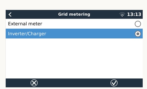
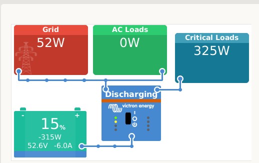
I am new to Victron products and have started setting up a 48V LiFeP04 battery system with a MultiPlus II 48/5000/70-50. In phase 1, my target now is to store electricity from the grid to the battery pack during low rate period at night and then use the stored electricity during day time. I am planning to add a PV system in phase 2 after I have got familiar with the Victron products.
Below is the diagram of my setup:
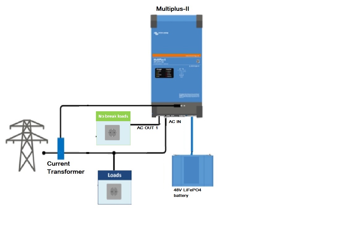

In VEConfig, I have the following settings:
TAB: General
System frequency 50Hz
Shore current 100.0 A
Overruled by remote unchecked
Dynamic current limiter unchecked
External current sensor connected (see manual) checked
State of charge when Bulk finished 90.0 %
Battery capacity 277 Ah
Charge efficiency 0.95
TAB: Grid
Country / grid code standard UK: G98/1 March 2019, G99/1 May 2018
LOM detection AC input 1 Type B (grid code compliant)
start P(f) at 50.40 Hz
start delay for p(F) 0.08 s
Droop for p(F) 10.0 %
Use Aux1 (if available) as disable FeedIn signal checked
Reactive power regulation Use a fixed Cos Phi
Filter time for reactive power 3.3 s
Cos phi at point 1 1.00
TAB: Inverter
PowerAssist unchecked
Inverter output voltage 230 V
Inverter DC shut-down voltage 48.00 V
Inverter DC restart voltage 50.00 V
Low DC alarm level 49.00 V
Do not restart after short-circuit (VDE 2510-2 safety) unchecked
enable AES unchecked
TAB: Charger
Enable charger checked
Weak AC input unchecked
Stop after excessive bulk checked
Lithium batteries checked
Configured for VE.Bus BMS unchecked
Charge curve Fixed
Absorption voltage 55.00 V
Float voltage 52.00 V
Charge current 70 A
Repeated absorption time 1.00 Hr
Repeated absorption interval 7.00 Days
Absorption time 1 Hr
TAB: Virtual switch
TAB: Usage
Virtual switch usage Do not use VS
TAB: Assistants
TAB: Assistant Configuration
ESS (Energy Storage System) (size:962)
*) System uses LiFePo4 with other type BMS
(This can be either a BMS connected via CAN bus or a BMS system in which the
batteries are protected from high/low cell voltages by external equipment.)
*) The battery capacity of the system is 277 Ah.
*) Sustain voltage 49.00 V.
*) Cut off voltage for a discharge current of:
0.005 C= 48.00 V
0.25 C= 48.00 V
0.7 C= 48.00 V
2 C= 48.00 V
*) Inverting is allowed again when voltage rises 2.00 V above cut-off(0).
*) Relevant VEConfigure settings:
- Battery capacity 277 Ah.
- PowerAssist unchecked
- Lithium batteries checked
- Dynamic current limiter unchecked
- Storage mode unchecked
In VenusOS - ESS, I have the following settings:
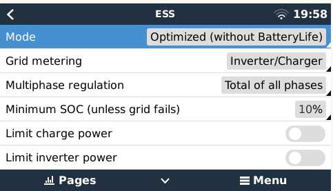
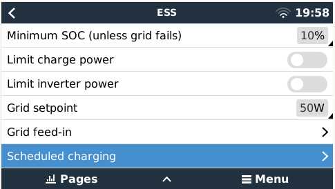
From the VenusOS screen shown below, it seems that the ESS system was working properly as per my expectation that:
- Discharge the battery to supply the loads of the house
- The grid setpoint was kept at around 50W
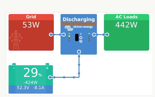
However, I have the following queries (or encountered some problems):
- While the VenusOS screen showed that the grid setpoint was kept at around 50W, a clamp ammeter at the CT point location showed that the grid was supplying 2.3A (i.e. around 520W) to the house at the same moment. That was 10 times larger than the grid setpoint. When the house asked for more load, the grid setpoint in the VenusOS screen still showed 50W and the clamp ammeter also showed around 2.3A. It seems that ESS thought that it was keeping the grid setpoint at 50W but in fact the power supplied from the grid was much more than that. What was causing such discrepancy? (Note: The chance of a faulty CT is low because I tried 2 CTs. Both had the same result.)
- Before the turning on of the MP-II, the clamp ammeter showed that the house was drawing 2.7A from the grid. After the MP-II was turned on, ESS then worked as shown in the above VenusOS screen. In that screen, you can see that the battery was giving 424W. The grid was giving (from the clamp ammeter) 2.3A or 529W at the same moment and therefore the total was 424 + 529 = 952W. However, before the turning on of the MP-II, the house was only using 2.7A or 621W. There was a more than 300W differences. Did it mean that the MP-II was itself eating up 300W? Or, such confusing figures were also caused by the cause of problem 1 above?
- In the VenusOS screen, only one “AC Load” was shown. I got that the "AC Load" shown also included the load connected to AC-Out1 (i.e. the critical load). Is it possible to show the load at AC-Out1 in a separated box? If yes, how?
Thank you very much in advance for any help/advice.

