Hello,
After few days i found out solution and i have tested this 'system' to start generator with impuls.
For me its working like a harm but im more than happy to hear from people more experienced than me.
It ll be handy for you if you have generator with push start button (standard car 12v engine start button).
It took me a while to get it sorted in head and i had done few tests + i got some help from outside ofc. *thx reddit with realys trick*.
Once you have this button:
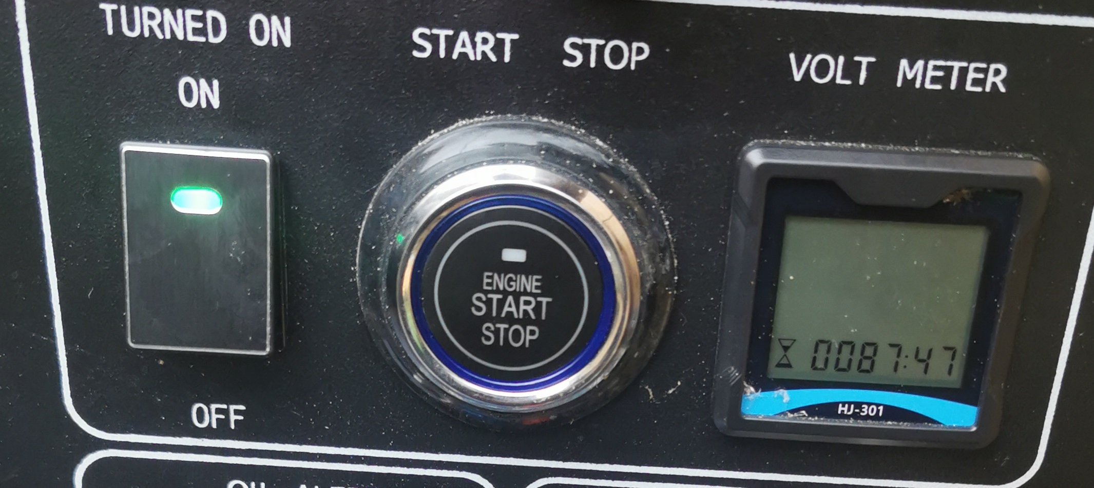
Im almost sure that you got build in 12v battery in your generator.
You can find this button in most of Chinese or branded generators that came of 'my friends'. Most of buttons works same way if not all... :)
Why you might need this?
To activate start and stop system you need to join two wires together with is 'Plus and Minus'
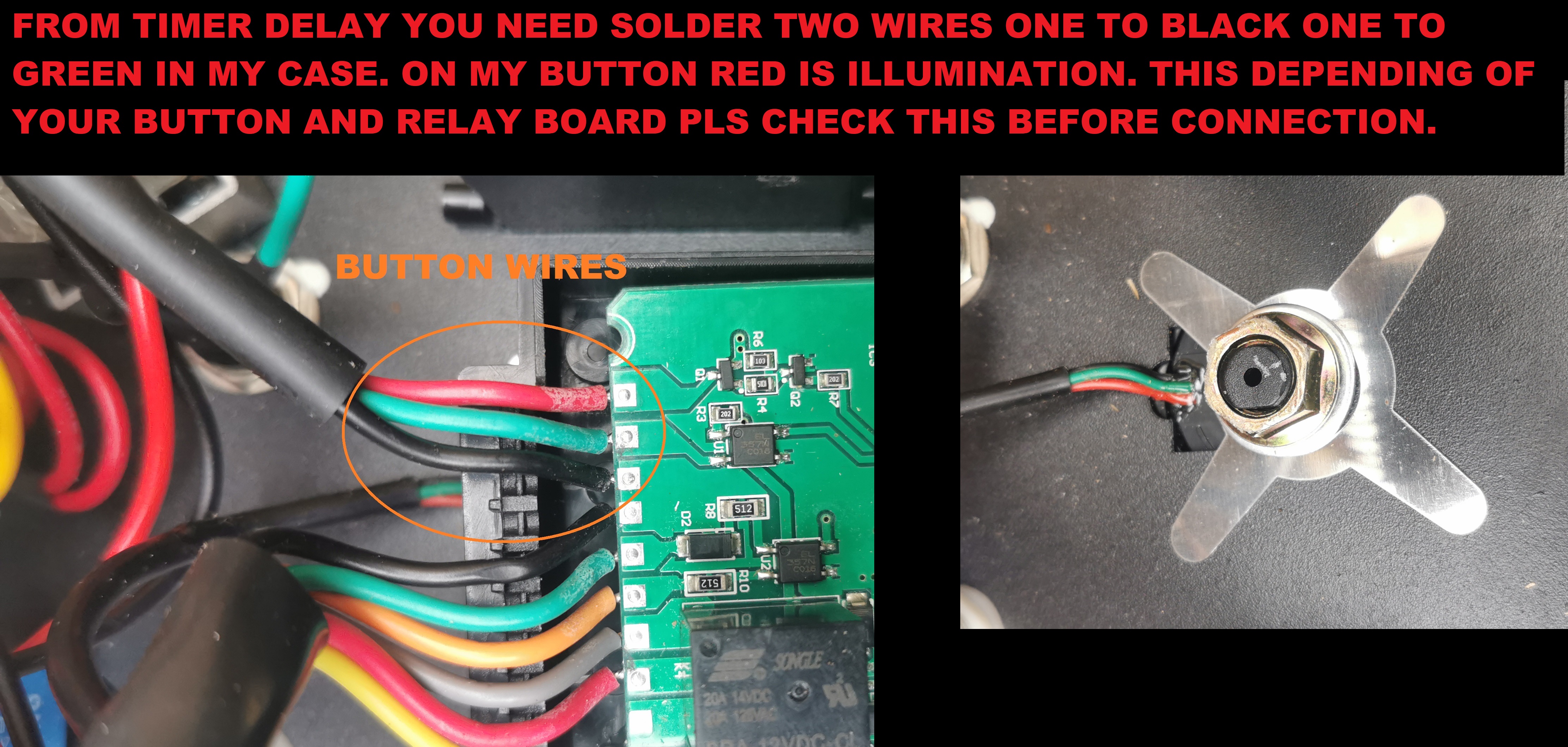
Start and Stop buttons has 3 wires- Plus, Minus and Illumination.
Because relay in CERBO is 'ON/OFF'. It gives constant output on COM wire.
Ok that's no problem when you wants to start generator but what if you start generator remotely and how would you turn it off?
*You can hit 'turn off' on CERBO that means you ll only loose power on COM wire- that's not way.
Then you have to hit 'turn on' to trigger wires and then AGAIN to turn it off.
Cerbo cannot be programmed to send just a signal on COM wire. Relay is constant open or closed. BAD/ WRONG/ SAD.
My tutorial ll costs you probably 30mins to 1hr of work depending of your skills and 10euro, depending how tidy you need it done etc.
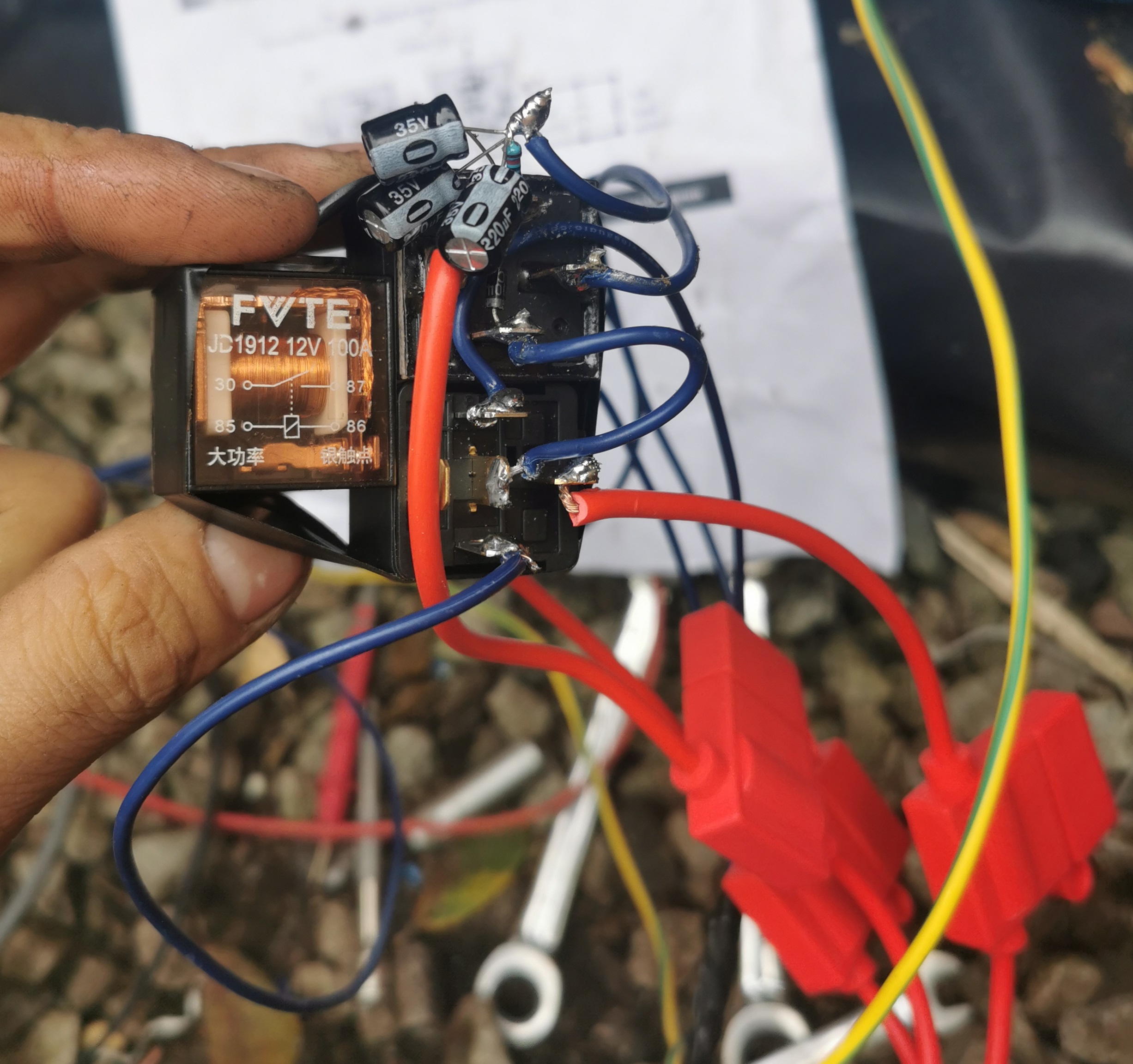
On pics below that i attached i ll show you my 'test' modules that needs to be redone and need some 3d printed case to get it nice and tidy.
What we need;
*Bit of cable.
*3-4 fuses 10A + fuse holders.
*Trigger Delay Timer- model JZ-801 (can be got on ali for 3 euro or amazon for 10.)
*2x 4 pin 12v relay
*1x 5 pin 12v relay)
*Wire terminals
*Soldering Iron
*6x 220uf Capacitors
*2x 10 Resistor
*x 1N4007 Diode
On diagram below (thanks the12volt.com) I show how i have everything connected. Instead of 1kUf resistor i used 3x 220uf.
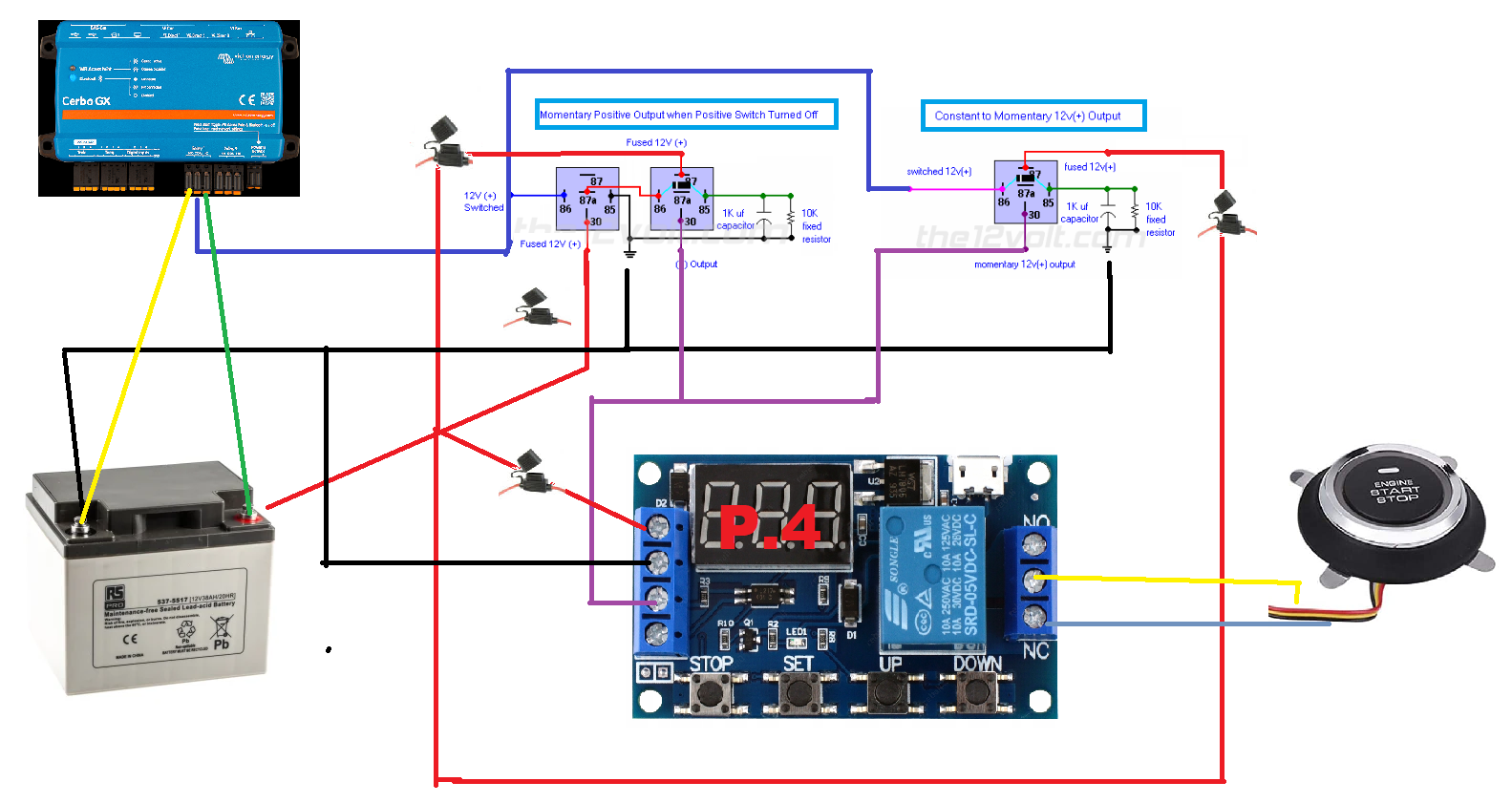
*** TRIGGER DELAY TIMER RUNS ON PROGRAM 4 AND SET FOR 1 SEC. ***
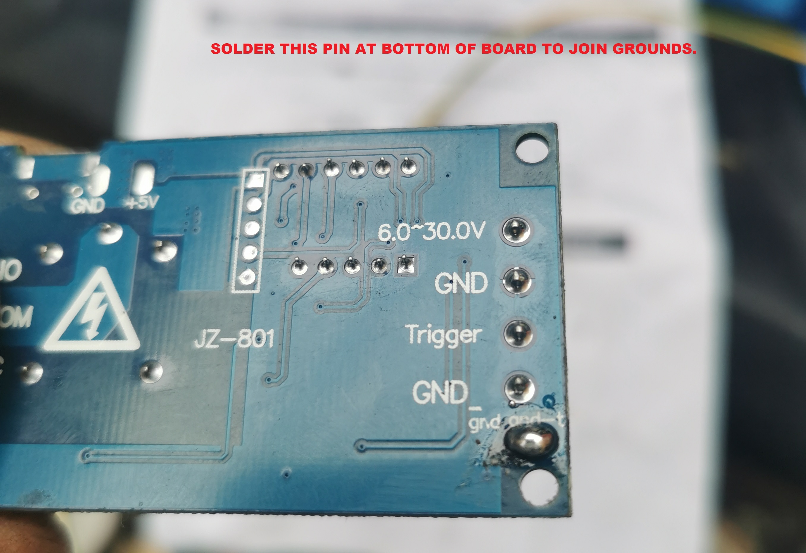
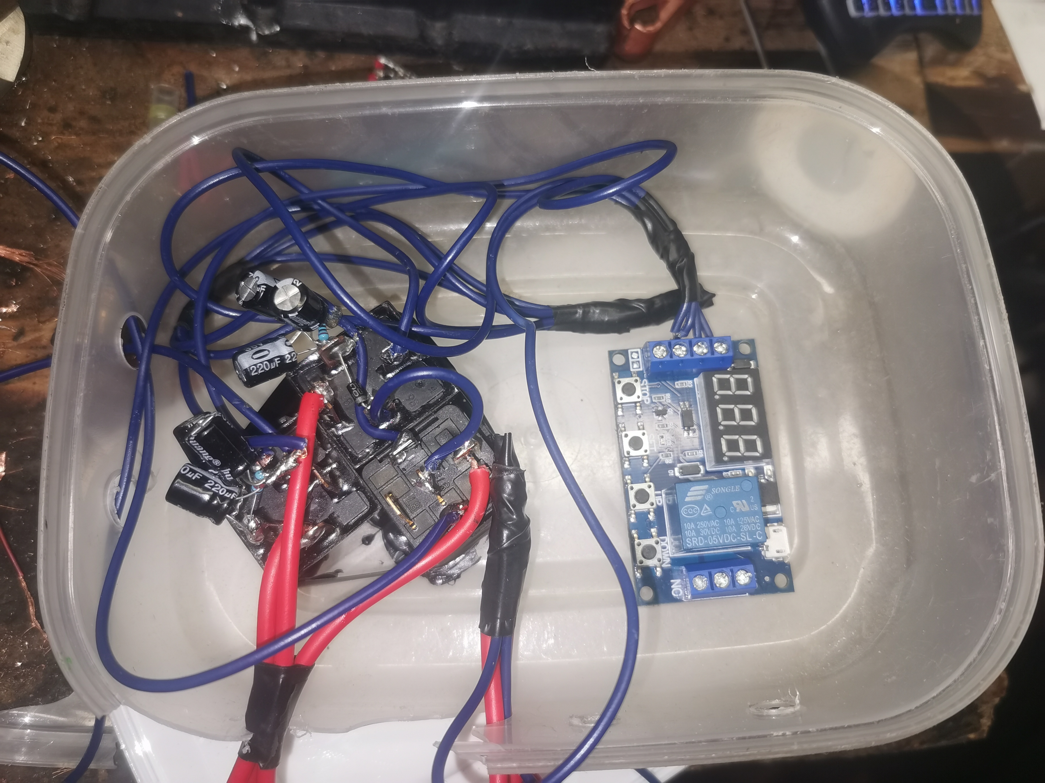
Here some quick notes from the12volt.com;
Constant to Momentary Output - Positive Input/Positive Output Relay Wiring Diagram
The capacitor allows the coil of the relay to be energized until the capacitor stores a charge, thus de-energizing the coil. The resistor bleeds off the charge of the capacitor when positive voltage is removed from the other side of the coil. You can increase the output time by simply changing the value of the capacitor. This one will give you about a 1/2 second output.
Momentary Positive Output when Positive Switch Turned Off Relay Wiring Diagram
When the switch is turned off, the coil of the first relay is de-energized closing the normally closed contacts and sends 12V (+) to the coil of the second relay. The capacitor allows the coil of the second relay to be energized until the capacitor stores a charge, thus de-energizing the coil. The resistor discharges the capacitor when positive voltage is removed from the other side of the coil when the switch connected to the first relay is turned back on. You can increase the output time by simply changing the value of the capacitor. This one will give you about a 1/2 second output.
