The standard readings suggest to use a relay to control the remote control pins of a multiplus or inverter. But relays are bulky, costly, prone to failure and use a measureable amount of power.
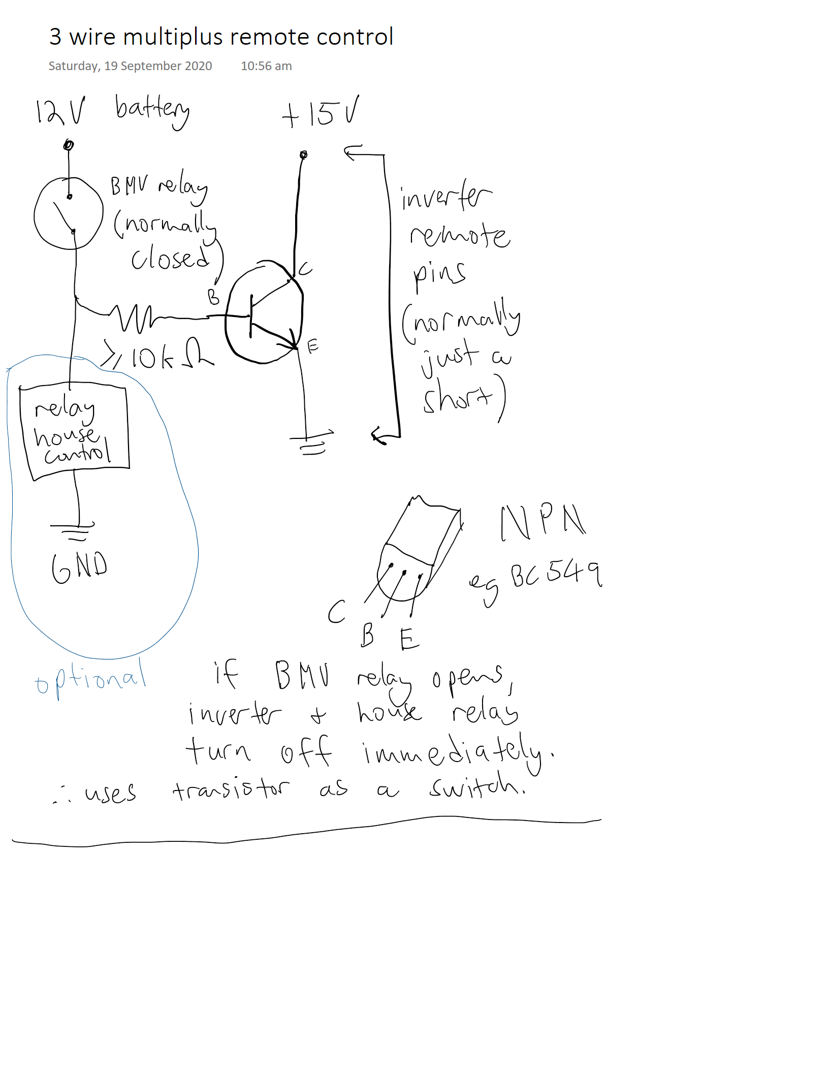
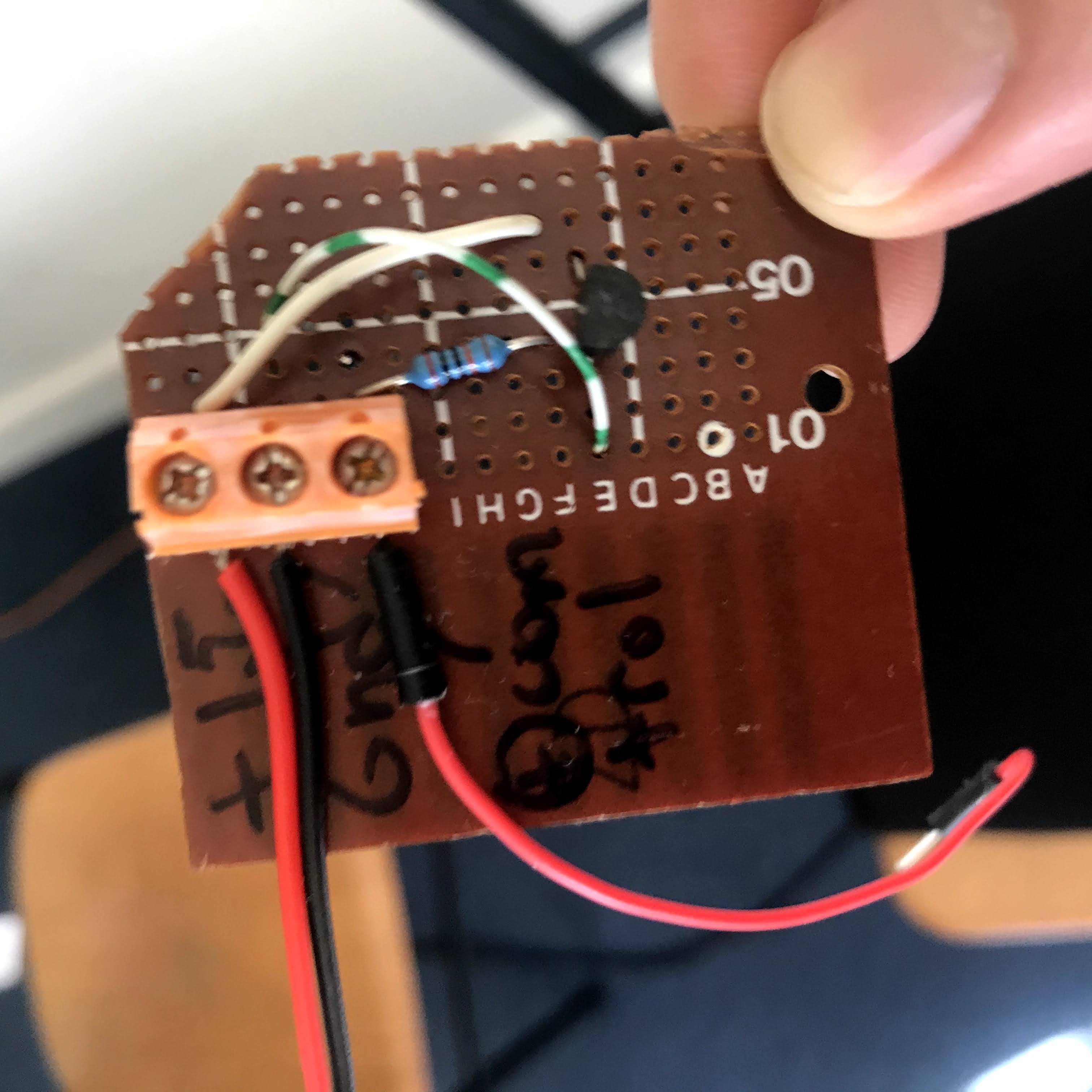
I put together a very simple circuit using only a resistor and a NPN transistor, which uses virtually no power, should be more reliable and possibly faster to respond to state changes. I've just soldered the components (badly) onto a small prototyping board. Make sure your copper is clean if you want a tidier result!
The only possible downside I've noted is that as the house (control) voltage dips below 12V it may not be adequate to keep the transister "closed" and the multiplus stopped inverting prematurely, but that has been hard to replicate in my system with a lithium battery since it is hard (and generally undesirable) to push the voltage lower than 12V anyway. Deep cycling lead acid systems might want to test this region in more detail, perhaps using a lower value resistor might help, though I've found anything lower than 10k to not work at all.
This device actually uses 3 wires, though 2 of them are just connecting to the remote terminals, and only 1 wire has to go to the input. High (>12V) equals on, low voltage will switch off. Higher house voltages should also work without modification but test carefully, I haven't. You'll need a multimeter to determine which of the multiplus or inverter's pins is positive and which is common ground - mine delivered a fraction of a milli amp when shorted and measured about 15V when open.
I haven't used a fuse, in theory it would be useless since the 100k resistor is unlikely to fail as a short, but something small like a 100mA quick blow fuse wouldn't hurt.
Any thoughts? Any dangers I haven't thought of?


